
Laser interferometer optical path difference location method and system

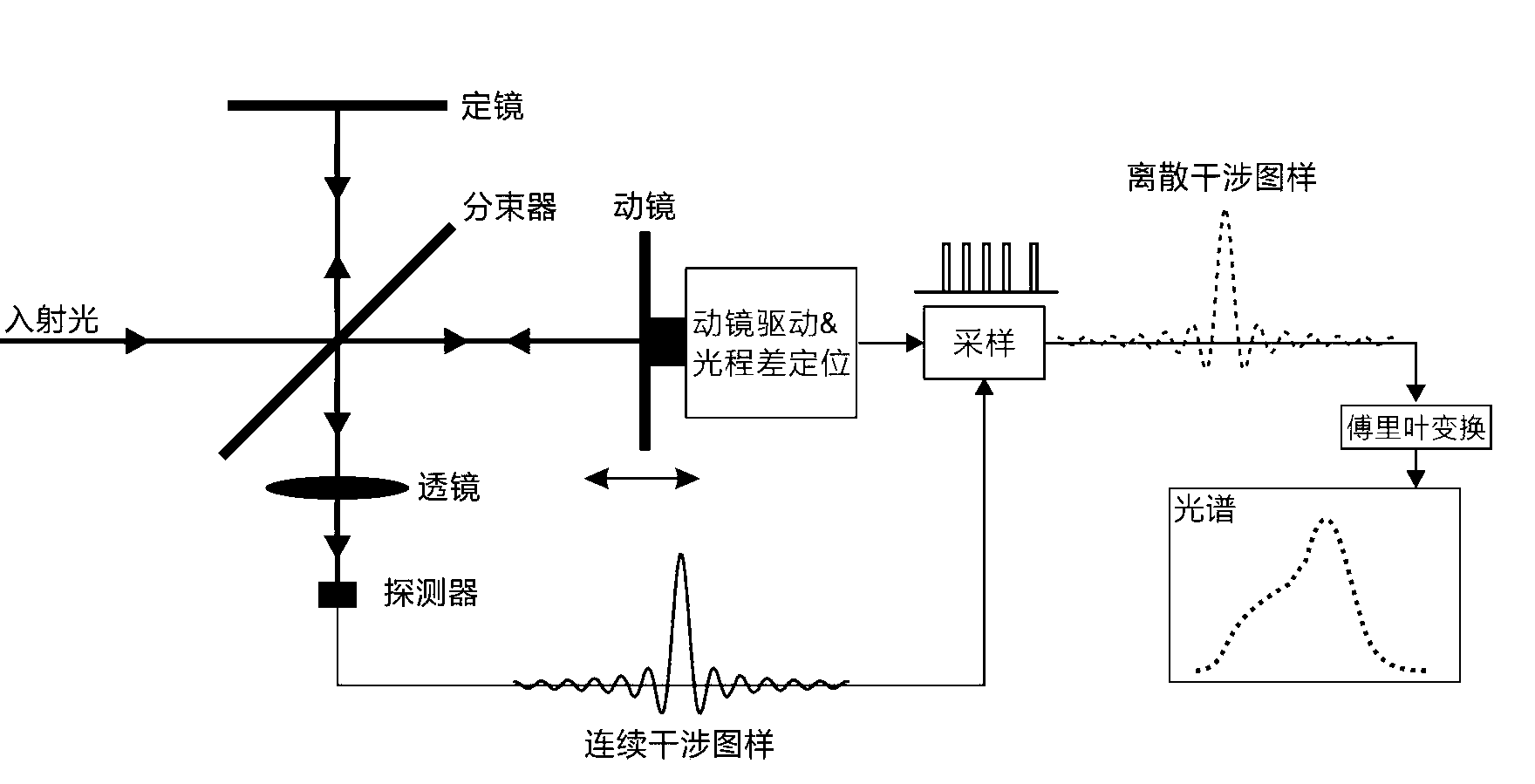
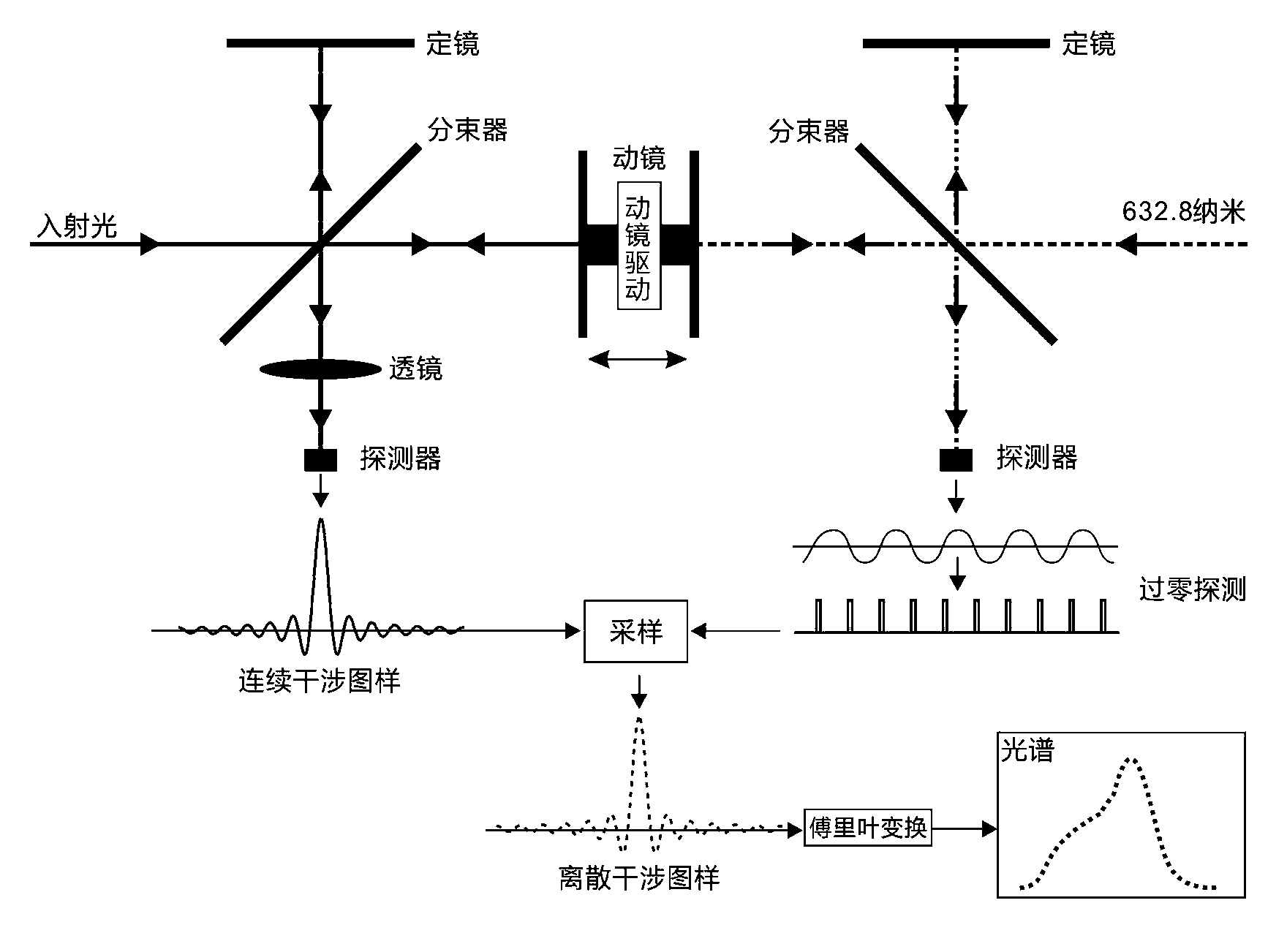
A technology of laser interferometer and positioning method, which is applied in the direction of spectrometry/spectrophotometry/monochromator, radiation pyrometry, instruments, etc., which can solve the problem of poor high-precision sampling, the inability to achieve equal optical paths, and inappropriate Conventional instrumentation and other issues to achieve the effect of high measurement accuracy

Active Publication Date: 2013-05-01
深圳市趣方科技有限公司
View PDF7 Cites 22 Cited by
  • Summary
  • Abstract
  • Description
  • Claims
  • Application Information

AI Technical Summary

Problems solved by technology

However, these methods have some intolerable shortcomings, such as: high-precision sampling with equal optical path difference cannot be achieved; high-precision positioning can only be achieved at a very short distance; environmental factors such as temperature and pressure are demanding; the cost is too expensive, Not suitable for routine instrumentation, etc.

Method used


Image

  • Laser interferometer optical path difference location method and system
  • Laser interferometer optical path difference location method and system
  • Laser interferometer optical path difference location method and system

Examples


Embodiment Construction

[0026] In order to clearly illustrate the technical features of the solution, the solution will be described below through a specific implementation manner.

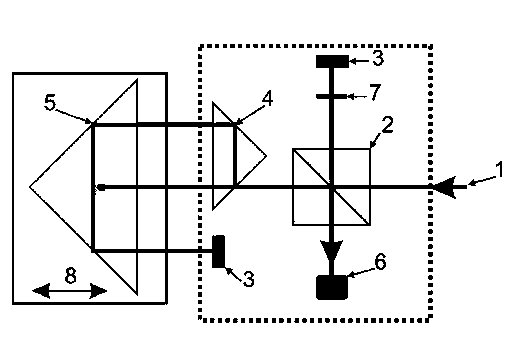
[0027]As shown in the attached figure, a laser interferometer optical path difference positioning method, the collimated beam from the laser shoots to the cube beam splitter, the reflected light reflected by the cube beam splitter shoots to the fixed mirror, and returns to the fixed mirror after being vertically reflected by the fixed mirror. The cube beam splitter; the collimated beam passes through the cube beam splitter and the part of the light beam is directed to the moving large pyramid retroreflector and then is retroreflected to the fixed small pyramid retroreflector; the small pyramid retroreflector is retroreflected After being retroreflected by the reflector, it shoots to the moving large pyramid retroreflector again; then it is reflected by the large pyramid retroreflector to the fixed plane reflector again; f...


PUM


Abstract

The invention discloses an optical path folding laser interferometer system which is simple and compact in structure and used for precisely locating the difference of two optical paths of a movable mirror and a stationary mirror of a Fourier transform spectrometer. By combining a pyramidal retroreflector and a reflecting mirror, which are compact in spatial layout, the optical path of a movable arm of the laser interferometer are folded for four times, and the period of an interference pattern generated by the interferometer is reduced by four times. Through the photoelectric transformation of a zero-passage detection circuit, a pulse signal with identical optical path difference interval being less than 100 nanometers, and a detector for triggering the Fourier transform spectrometer is used for sampling the interference pattern of a signal to be detected. Due to the adoption of the laser interferometer system, not only can the working spectrum of the Fourier transform spectrometer be expanded to near ultraviolet (to 350 nanometers) of a shortwave band, but also the high measurement precision advantage of the Fourier transform spectrometer can be maintained. Therefore, an ultraviolet-visible light Fourier transform spectrometer which is realized through the method and the system can be widely applied in multiple fields such as chemistry, biology, medicine, materials and optics.

Description

technical field [0001] The invention relates to a laser interferometer optical path difference positioning method and system. Background technique [0002] Compared with dispersive spectrometers, Fourier transform spectrometers have the following obvious inherent optical characteristics advantages in the long-wave infrared band: 1 Multi-channel (Multiplex); 2 High luminous flux (Throughput); 3 High spectral measurement accuracy (Connes); 4 Wide measurement band; 5 high / tunable spectral resolution; 6 consistent resolution across all bands. Therefore, Fourier transform spectrometer is widely used in the measurement of infrared absorption spectrum, and is more widely called Fourier transform infrared spectrometer. Fourier transform infrared spectrometer can perform qualitative and quantitative analysis on samples, and has the characteristics of high signal-to-noise ratio, good reproducibility and fast scanning speed, etc. identification, forensic identification and other fie...

Claims


Application Information

Patent Timeline
IPC IPC(8): G01J3/02G01J3/06
Inventor 李剑平
Owner 深圳市趣方科技有限公司
Learn More