Device and method for switching stepped capacitor group

A capacitor bank and ladder-type technology, applied in the direction of circuit devices, electrical components, system integration technology, etc., can solve problems such as overcompensation, inability to change, unbalanced power grid, etc., to avoid overcompensation or undercompensation problems, and overcome IO line problems. Insufficient quantity and the effect of avoiding manual misoperation

Active Publication Date: 2013-05-01
JINZHOU WANSHI SPECIAL TRANSFORMER
View PDF4 Cites 10 Cited by
  • Summary
  • Abstract
  • Description
  • Claims
  • Application Information

AI Technical Summary

Problems solved by technology

At present, reactive power compensation automatic switching devices have been widely researched and applied. The existing reactive power compensation switching control devices and methods have the following problems: 1) It is mainly for switching capacitor banks with equal capacity, and the amount of reactive power compensation The change is relatively large, and it is often in an over-compensated or under-compensated state, which has a large impact on the power grid; 2) Switching is mainly based on power factor. During light-load operation, switching actions are frequent, and it is difficult to ensure the required reactive power. ;3) The switching methods of overall switching and split-phase switching are not flexible. Once selected, they cannot be changed during operation. The three-phase unbalance of the power grid even worsens the unbalance problem of the power grid; 4) The online monitoring of power quality, reactive power compensation, fault diagnosis, and remote communication and remote control have not been well combined

Method used


Image

  • Device and method for switching stepped capacitor group
  • Device and method for switching stepped capacitor group
  • Device and method for switching stepped capacitor group

Examples


Embodiment Construction

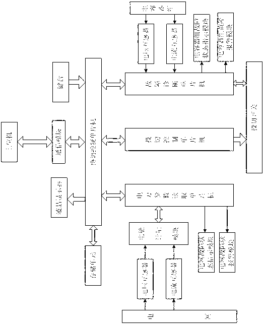
[0038] Such as figure 1 As shown, the stepped capacitor bank switching device is composed of a power parameter reading single-chip microcomputer system, a switching control single-chip microcomputer system, a fault diagnosis single-chip microcomputer system and a coordination control single-chip microcomputer system. The power parameter reading single-chip microcomputer system consists of a first voltage mutual inductance device, a first current transformer, an electric energy metering module, a power grid fault status indication system, a power grid fault sound and light alarm system, and a power parameter reading single-chip computer; the fault diagnosis single-chip microcomputer system consists of a second voltage transformer, a second current transformer , fault diagnosis single-chip microcomputer, auxiliary contact of switching switch, capacitor bank fault state indication system and capacitor bank fault sound and light alarm system; the switching control single-chip micro...


PUM


Abstract

The invention discloses a device and a method for switching a stepped capacitor group. By the device and the method, the electric energy quality can be monitored in real time and can be subjected to reactive switching control, meanwhile the device has a fault diagnosis function on the capacitor group and a switching switch, and the reliability of a system is increased. The device consists of an electric energy parameter reading single chip system, a switching control single chip system, a fault diagnosis single chip system and a coordinate control single chip system, wherein the electric parameter reading single chip system consists of a first voltage mutual inductor, a first current mutual inductor, an electric energy metering module, a grid fault state indicating system, a grid fault sound-light alarm system and an electric energy parameter reading single chip; and the fault diagnosis single chip system consists of a second voltage mutual inductor, a second current mutual inductor, a fault diagnosis single chip, auxiliary contacts of the switching switch, a capacitor group fault state indicating system and a capacitor group fault sound-light alarm system. The four single chips form a sub-system with host machine-client machine relation, can finish respective task independently and can also work cooperatively.

Description

technical field [0001] The invention relates to an automatic control device for reactive power compensation in an electric power system, in particular to a stepped capacitor bank switching device and a switching method thereof. Background technique [0002] In recent years, with the rapid development of my country's economy and the improvement of people's living standards, the load of substations has increased rapidly, and the inductive loads such as motors and transformers have also increased rapidly. The capacity required for reactive power compensation and the demand for high-quality electric energy have also increased. , while the terminal substation load changes greatly. [0003] The installation of reactive power compensation devices in the power system is a major measure to maintain high-quality operation of the power grid, and it is also a major topic in the field of power system research today. It is a compensation method widely used at home and abroad. my country s...

Claims


Application Information

Patent Timeline
Patent Type & Authority Applications(China)
IPC IPC(8): H02J3/18H02J13/00
CPCY04S10/22Y02E40/30Y02E40/74Y02E40/70
Inventor 巫庆辉于忠党于震丁硕杨友林杨祯山韩建群刘闯张博
Owner JINZHOU WANSHI SPECIAL TRANSFORMER
Why Eureka
Try Eureka