Super-resolution microscope method and device based on random fluorescence bleaching

A fluorescent bleaching and super-resolution technology, which is applied in the field of optical super-resolution microscopy, can solve the problem that fluorescent dyes cannot be directly applied, and achieve the effects of high system signal-to-noise ratio, simple structure, and simple device structure.

Inactive Publication Date: 2013-05-08
ZHEJIANG UNIV
View PDF3 Cites 21 Cited by
  • Summary
  • Abstract
  • Description
  • Claims
  • Application Information

AI Technical Summary

Problems solved by technology

[0005] STED is one of the mainstream super-resolution methods at present, but this super-resolution method needs to integrate new modules or devices on the basis of traditional confocal microscopes, and these modules or devices are often more expensive
PALM and STORM use the randomness of fluorescent molecular light emission to achieve super-resolution by sparsely act

Method used


Image

  • Super-resolution microscope method and device based on random fluorescence bleaching
  • Super-resolution microscope method and device based on random fluorescence bleaching
  • Super-resolution microscope method and device based on random fluorescence bleaching

Examples


Embodiment 1

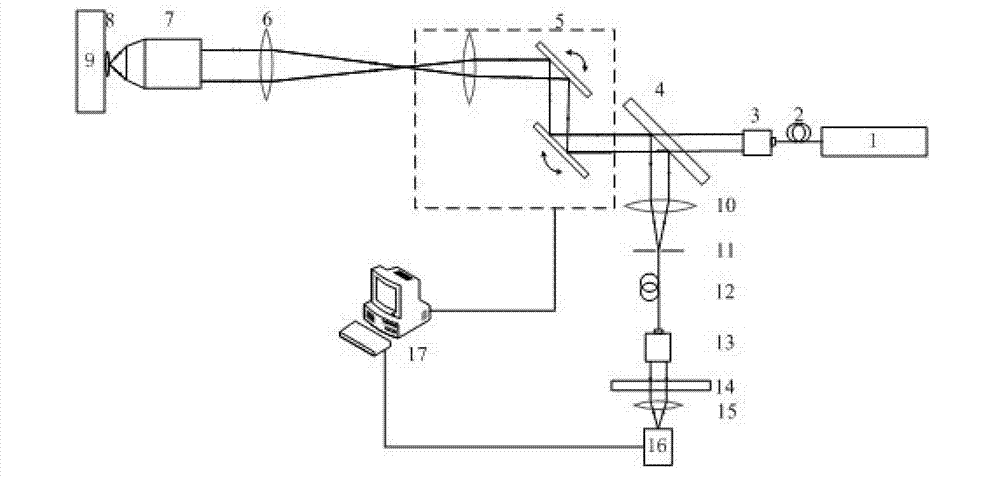
[0042] like image 3 As shown, a monochromatic super-resolution microscopy device based on random fluorescence bleaching, including: a laser 1, a single-mode fiber 2, a first fiber collimator 3, a dichromatic mirror 4, a scanning galvanometer system 5, and a field mirror 6 , microscope objective lens 7, sample to be measured 8, sample stage 9, first lens 10, pinhole 11, detection fiber 12, second fiber collimator 13, optical filter 14, second lens 15, photomultiplier tube ( PMT) 16, main control computer 17.

[0043] Among them, the laser 1 emits a laser beam, and the single-mode fiber 2, the first fiber collimator 3, the dichroic mirror 4, the scanning galvanometer system 5, the field lens 6, the microscopic objective lens 7 and the sample stage 9 are sequentially arranged in the optical path of the laser beam. on the optical axis. The first fiber collimator 3 collimates the laser beam, the dichroic mirror is used to transmit the excitation light and reflect the fluorescenc...

Embodiment 2

[0058] By adding an excitation light module and a detection module, it is possible to make Figure 4 The shown setup is used for two-color super-resolution microscopy based on stochastic fluorescent bleaching (for samples labeled with two fluorescent dyes, and it is required that the fluorescence wavelengths emitted by the two fluorescent samples are different). Figure 4 and image 3 In comparison, another excitation light module is placed at the excitation light end, including an additional laser 18, an additional single-mode fiber 19, an additional fiber collimator 20 and an additional dichroic mirror 21 matching the wavelengths of the two excitation lights, and the additional dichroic mirror The function of 21 is to make the two excitation lights coincide in space; at the same time, a detection module is correspondingly added at the detection end, including an additional PMT25, an additional lens 24, an additional color filter 23 and a detection dichroic mirror 22 matched ...


PUM


Abstract

The invention discloses a super-resolution microscope method based on random fluorescence bleaching. The super-resolution microscope method comprises the following steps of: 1, focusing a laser beam on a to-be-detected sample with a fluorescence mark, exciting the to-be-detected sample by the laser beam to emit fluorescent; 2, collecting the fluorescent emitted by the to-be-detected sample to obtain fluorescent strength information; 3, arranging an area-of-interest on the to-be-detected sample, bleaching the area-of-interest, collecting the fluorescent strength information of the fluorescent emitted from the to-be-detected sample in a bleaching process; and 4, comparing and analyzing the fluorescent strength information by a computer to obtain position information of a fluorescent molecule in the area-of-interest, and obtaining a super-resolution image by using a restructing algorithm. The invention also discloses a super-resolution microscope device based on random fluorescence bleaching. The super-resolution microscope device has the advantages of simple structure, high transverse resolution and high signal to noise ratio.

Description

technical field [0001] The invention belongs to the field of optical super-resolution microscopy, in particular to a super-resolution microscopy method and device based on random fluorescence bleaching. Background technique [0002] With the development of science and technology, people are constantly pursuing smaller and smaller size structures and higher resolution capabilities, especially in the fields of microelectronics, aerospace, nanoprocessing, life sciences and materials engineering. demands are becoming increasingly urgent. [0003] Although electron microscopes, atomic force microscopes, scanning electron microscopes, and near-field scanning microscopes have high resolving power, their high requirements for samples or operating environments and their dependence on probes greatly limit their application range. Far-field optical microscopy has the characteristics of no contact and less damage to the sample, but according to Abbe's imaging theory, its resolution is ...

Claims


Application Information

Patent Timeline
IPC IPC(8): G01N21/64
Inventor 匡翠方王轶凡刘旭
Owner ZHEJIANG UNIV
Why Eureka
Try Eureka