Carbon nano tube field effect tube of double-material underlap heterogeneous grid structure

A technology of carbon nanotubes and field effect tubes, which is applied in the field of structural optimization of device performance, can solve problems such as device performance degradation, achieve high current switching ratio, low leakage current, and suppress the effect of leakage-induced barrier reduction

Active Publication Date: 2013-05-08
NANJING UNIV OF POSTS & TELECOMM INST AT NANJING CO LTD
View PDF4 Cites 5 Cited by
  • Summary
  • Abstract
  • Description
  • Claims
  • Application Information

AI Technical Summary

Problems solved by technology

[0007] technical problem: The purpose of the present invention is to solve the problem that the traditional carbon nanotube field effect tube will have a bipolar effect, and as the device size continues to shrink, there will be a short channel effect that will cause a decline in device performance. Conside

Method used


Image

  • Carbon nano tube field effect tube of double-material underlap heterogeneous grid structure

Examples


Example Embodiment

[0018] The idea of ​​the present invention will be described in further detail below in conjunction with the drawings.

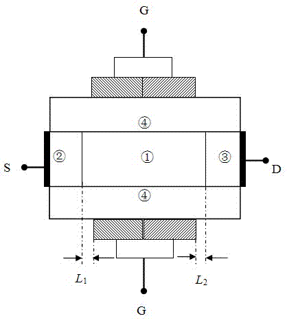
[0019] figure 1 It is a schematic diagram of the vertical cross-sectional structure of the present invention.

[0020] Such as figure 1 As shown, the conductive channel 1, the source region 2 and the drain region 3 are all made of carbon nanotube materials, a fundamental semiconductor carbon nanotube is selected, and the middle part is used as a carbon nanotube field with a dual-material under-stack heterogeneous gate structure Conductive channel 1 of the effect tube. After the two ends of the intrinsic semiconductor carbon nanotubes are heavily doped with molecules or metal ions, they are used as the source regions of the carbon nanotube field effect tube with a bi-material under-stack heterogeneous gate structure. 2. Drain region 3; outside the conductive channel 1, source region 2 and drain region 3, a layer of gate oxide layer 4 is formed by atomic depositi...


PUM


Abstract

The invention discloses a carbon nano tube field effect tube of a double-material underlapped heterogeneous grid structure. The field effect tube comprises a conductive ditch channel (1), a source area (2), a drain area (3), a grid electrode oxidation layer (4), a source electrode (S), a drain electrode (D) and a grid electrode (G). The conductive ditch channel (1), the source area (2) and the drain area (3) are all made of carbon nano tube materials. The grid electrode oxidation layer (4) is generated outside the conductive ditch channel (1), the source area (2) and the drain area (3) by utilizing methods of atom deposition and the like. A metal electrode layer is further precipitated outside the grid electrode oxidation layer (4). As a grid electrode (G) of the carbon nano tube field effect tube of the double-material underlapped heterogeneous grid structure, the grid electrode (G) utilizes two kinds of conductive metal with different work functions for manufacture so that a heterogeneous grid of the double-material underlapped heterogeneous grid structure is formed. Low leakage current ratio and high current switch ratio are achieved, a drain induced barrier lowering (DIBL) effect is restrained, and related performance index requirements of ITRS'10 can be well met.

Description

technical field [0001] The invention relates to the field of carbon nanotube field effect tubes, especially in the aspect of optimizing the structure of the carbon nanotube device to the performance of the device. [0002] Background technique [0003] Since Iijima [Iijima S . Helical Microtubules of Graphic Carbon[J]. Nature, 1991, 354(7): 56-58.] discovered carbon nanotubes in 1991, in understanding their basic properties and studying their potential engineering applications Important progress has been made [Baughman R H , Zakhidov A A , Heer W A D . Carbon nanotubes - the route toward applications[J]. Science, 2002, 297(5582): 787-792.]. Carbon nanotubes (CNTs) are seamless, hollow tubes rolled from graphene sheets formed of carbon atoms. Its special structure makes it have unique electrical, thermal, mechanical and other properties, and has important and broad application prospects in the fields of nanoelectronic devices and optoelectronic materials. Carbon nanotub...

Claims


Application Information

Patent Timeline
IPC IPC(8): H01L29/78H01L29/49B82Y10/00
Inventor 王伟夏春萍肖广然
Owner NANJING UNIV OF POSTS & TELECOMM INST AT NANJING CO LTD
Why Eureka
Try Eureka