
Method and device for improving underwater wet welding joint structure property

A microstructure performance, wet welding technology, applied in the direction of welding equipment, welding accessories, arc welding equipment, etc., can solve the problems of increasing the burning loss of alloy elements, accelerating the crystallization speed of the welding pool, and fast cooling speed of the welding zone, etc., to achieve reduction Tendency to cold cracks, slow cooling rate, and reduce the effect of hardened structure

Inactive Publication Date: 2013-05-22
HARBIN INST OF TECH AT WEIHAI
View PDF5 Cites 14 Cited by
  • Summary
  • Abstract
  • Description
  • Claims
  • Application Information

AI Technical Summary

Problems solved by technology

Affected by the evaporation of water vapor, compared with land welding, the cooling rate of the welding pool is about 10-15 times that of land welding, so the crystallization speed of the welding pool is accelerated, and the content of diffusible hydrogen is higher, which will lead to pores The occurrence of welding defects such as cold cracks and cold cracks will reduce the serviceability and fatigue resistance of the welded structure; the influence of the oxidizing atmosphere will increase the burning loss of alloying elements and remain in the weld in the form of non-metallic inclusions, thus Reduce the mechanical properties of welded joints
This brings a series of adverse effects to underwater welding
[0005] In order to solve the problem of excessive cooling of the welding zone during underwater wet welding, researchers have used welding bead plus insulation layer, weld seam tempering technology (multi-layer multi-pass welding) or the method of using thermite electrode to carry out underwater welding. Wet welding, although it slows down the cooling rate of the weld to a certain extent, the effect is not obvious and the efficiency is not high

Method used


Image

  • Method and device for improving underwater wet welding joint structure property

Examples


Embodiment 1

[0022] A method for improving the microstructure and properties of underwater wet welded joints, comprising the steps of welding a welding sample with a welding torch underwater, and the step of preheating the welding surface of the welding sample before welding. Among them, preheating before welding adopts the method of adding intermediate frequency induction heating.

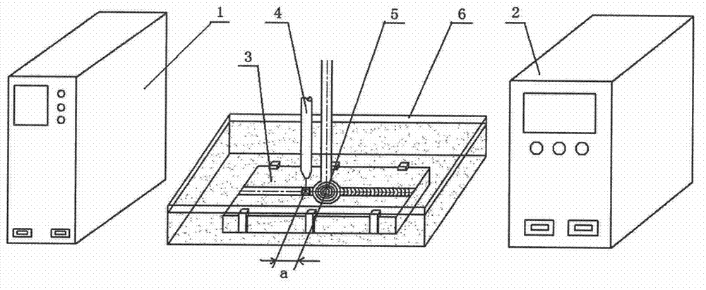
[0023] Such as figure 1 As shown, the device for improving the structure and performance of underwater wet welding joints corresponding to the above method includes an underwater welding power source 1, a welding torch 4 connected to the underwater welding power source 1, a welding sample 3, and a welding The welding water tank 6 outside the sample 3, the intermediate frequency induction heating coil 5 is placed on the upper surface of the welding sample 3, and the intermediate frequency induction heating coil 5 is controlled by the intermediate frequency induction heating power supply 2.

[0024] During weld...

Embodiment 2

[0026] A method for improving the microstructure and properties of underwater wet welded joints, comprising the steps of using a welding torch to weld a welding sample underwater, and performing pre-weld preheating and post-weld heat treatment on the welded surface of the welded sample . Among them, pre-welding preheating and post-welding heat treatment adopt the method of adding intermediate frequency induction heating.

[0027] Such as figure 1 As shown, the device for improving the structure and performance of underwater wet welding joints corresponding to the above method includes an underwater welding power source 1, a welding torch 4 connected to the underwater welding power source 1, a welding sample 3, and a welding The welding water tank 6 outside the sample 3, the intermediate frequency induction heating coil 5 is placed on the upper surface of the welding sample 3, and the intermediate frequency induction heating coil 5 is controlled by the intermediate frequency i...

Embodiment 3

[0030] A method for improving the microstructure and performance of underwater wet welded joints, comprising the steps of using a welding torch to weld a welding sample underwater, and the step of performing post-weld heat treatment on the welding surface of the welding sample. Among them, the post-weld heat treatment adopts the method of adding high-frequency induction heating.

[0031] Such as figure 1 As shown, the device for improving the structure and performance of underwater wet welding joints corresponding to the above method includes an underwater welding power source 1, a welding torch 4 connected to the underwater welding power source 1, a welding sample 3, and a welding The welding water tank 6 outside the sample 3, the high-frequency induction heating coil 5 is placed on the upper surface of the welding sample 3, and the high-frequency induction heating coil 5 is controlled by the high-frequency induction heating power supply 2.

[0032] During welding, the high-...


PUM


Abstract

The invention relates to the technical field of welding, and particularly relates to a method and a device for improving an underwater wet welded joint structure property. The method comprises the step that a welded sample is welded underwater through a welding torch and the step that weld preheating before welding and / or heat treatment after welding is conducted on the welded surface of the welded sample. Corresponding devices comprise an underwater welding power supply, the welding torch connected with the underwater welding power supply, the welded sample and a welding water groove arranged outside the welded sample. An induction heating coil is arranged on the upper surface of the welded sample and is controlled by an induction heating power supply. By adopting the method and the device for improving the underwater wet welded joint structure property, when heat treatment is effectively conducted on the welded sample, weld joint cooling speeds can meanwhile be slowed down, and accordingly the effects of reducing wet welding defects such as the number of weld joints, quenched structures of heat affected zones and cold crack inclination. Therefore, the method and the device for improving the underwater wet welded joint structure property are convenient to operate.

Description

technical field [0001] The invention relates to the field of welding technology, in particular to a method and a device for improving the structure and performance of underwater wet welding joints. Background technique [0002] As an important construction technology of marine steel structure, underwater welding has become an indispensable engineering method for marine energy development, ship maintenance, marine engineering construction and repair. Over the past few years, with the country's vigorous development of water conservancy and hydropower projects and the deployment of dangerous reservoir reinforcement projects, the maintenance and repair of underwater steel structures are also in great need of this underwater welding technology. [0003] Compared with other underwater welding methods, wet underwater welding has the following advantages: ①It can be directly used in underwater welding environment. ② No other auxiliary equipment is needed, and the movement is conven...

Claims


Application Information

Patent Timeline
IPC IPC(8): B23K9/32B23K9/00
Inventor 张洪涛袁新冯吉才胡乐亮代项羽
Owner HARBIN INST OF TECH AT WEIHAI
Learn More