

Numerical control mill groove machine tool
A machine tool and grinding tank technology, which is applied in the direction of grinding machines, grinding/polishing equipment, metal processing equipment, etc., can solve the problems of low part processing efficiency, long production cycle, low production efficiency, etc., and achieve stable processing quality and high degree of automation , the effect of high production efficiency
- Summary
- Abstract
- Description
- Claims
- Application Information
AI Technical Summary
Problems solved by technology
Method used
Image

Examples
Embodiment Construction
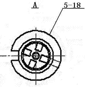
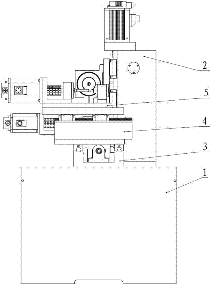
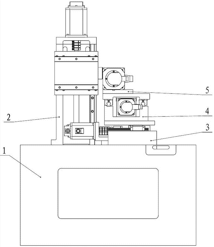
[0037] Refer to attached Figure 1-13 , The CNC groove grinding machine tool is composed of a bed 1, a lifting and moving part unit 2, a front and rear moving part unit 3, a left and right moving part unit 4 and a rotary fixture part unit 5.
[0038] The bed 1 is a casting machine body.
[0039] The lifting and moving part unit 2 is installed on the upper part of the bed 1 . The lifting and moving part unit 2 includes a lifting column 2-1, a lower end cover 2-2, a hexagon socket head screw 2-3, a deep groove ball bearing 2-4, a lower bearing seat 2-5, and a ball screw Deputy 2-6, lifting nut 2-7, hexagon socket head screw 2-8, lifting slide plate 2-9, upper bearing seat 2-10, two angular contact bearings 2-11, spacer ring 2-12, Upper end cover 2-13, hexagon socket head screw three 2-14, bushing 2-15, lock nut one 2-16, electric spindle base 2-17, hexagon head bolt 2-18, lifting motor seat 2-19 , Coupling one 2-20, hexagon socket head screw four 2-21, lifting servo motor 2-2...
PUM
 Abstract
Description
Claims
Application Information