Optical axis and thickness measurement method and device of differential confocal internal-focusing lens

A differential confocal and thickness measurement technology, which is applied in the direction of measuring devices, using optical devices, testing optical properties, etc., to achieve high axial resolution, reduce running distance, and increase depth

Inactive Publication Date: 2013-05-29
BEIJING INSTITUTE OF TECHNOLOGYGY
View PDF7 Cites 19 Cited by
  • Summary
  • Abstract
  • Description
  • Claims
  • Application Information

AI Technical Summary

Problems solved by technology

[0015] The purpose of the present invention is to solve the problem of non-contact high-precision measurement of lens optical axis and

Method used


Image

  • Optical axis and thickness measurement method and device of differential confocal internal-focusing lens
  • Optical axis and thickness measurement method and device of differential confocal internal-focusing lens
  • Optical axis and thickness measurement method and device of differential confocal internal-focusing lens

Examples


Embodiment 1

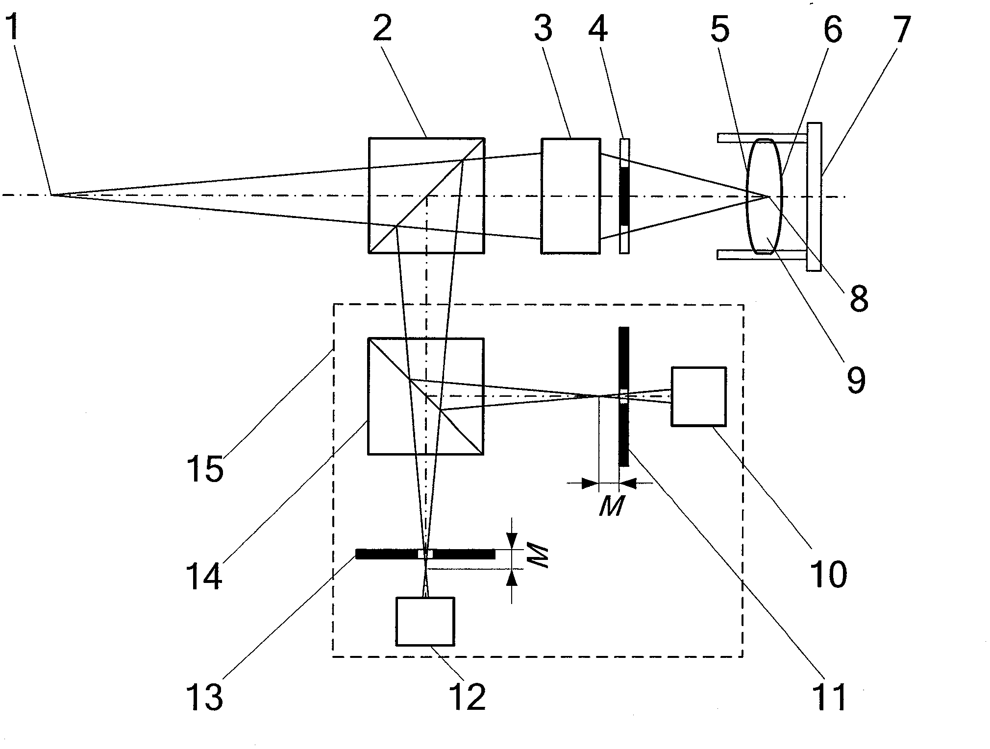
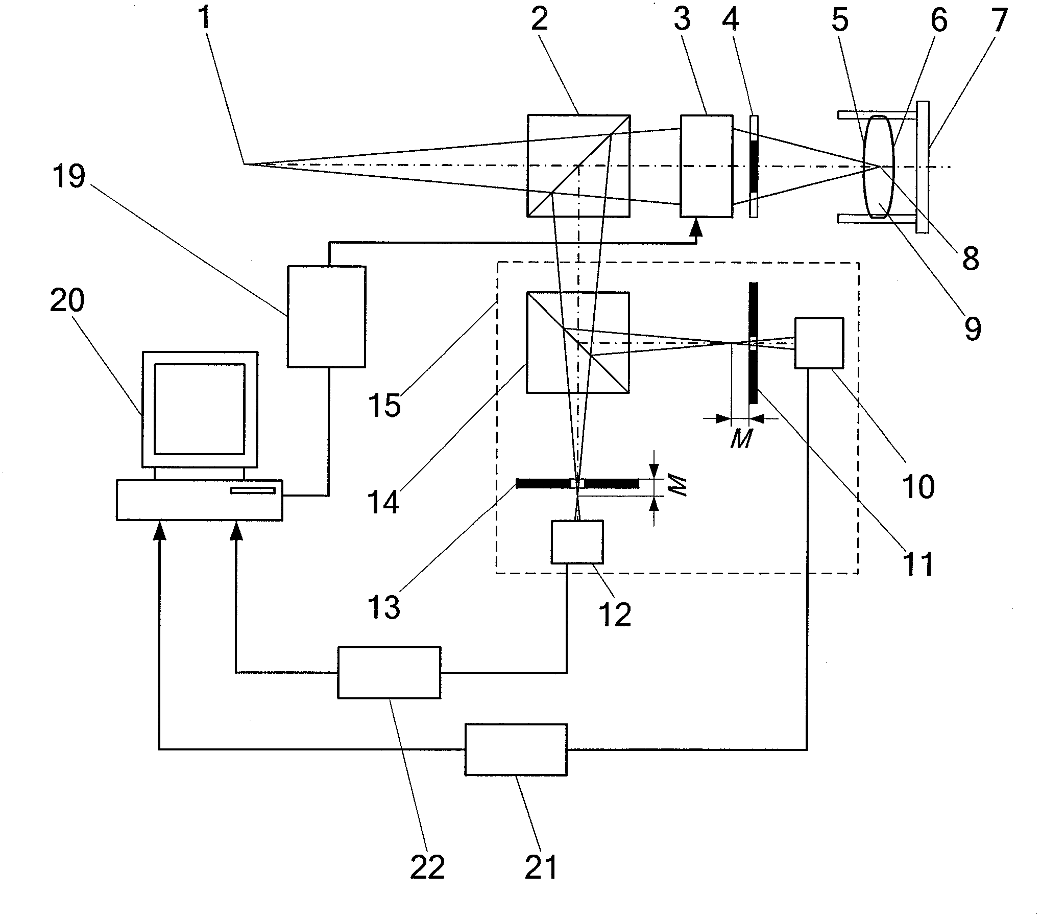
[0057] like Figure 7 As shown, the optical axis and thickness measuring device of the differential confocal inner focusing method lens includes a point light source generating device 18, which is sequentially placed in the first beam splitter 2, the inner focusing objective lens 3 and the ring light in the direction of the light emitted by the point light source 1. Pupil 4 also includes a differential confocal system 15 placed in the reflection direction of the first beam splitter 2, wherein the surface of the measured lens 9 and the first beam splitter 2 reflect the light beam to the second beam splitter in the differential confocal system 15 14; the second beam splitter 14 divides the light into two paths, the reflected light illuminates the CCD detector 30 after passing through the pinhole 11 after the focus, and the transmitted light illuminates the CCD detector 31 after passing through the pinhole 13 before the focus; the image acquisition card 32 collects the CCD detecti...

Embodiment 2

[0074] like Figure 4 and Figure 7 As shown, the embodiment 1 Figure 7 The differential confocal system in 15 is replaced by Figure 4 The differential confocal system 15 can constitute the second embodiment. The difference from Embodiment 1 is that after the light enters the differential confocal system 15 , the second beam splitter 14 splits the light into two paths, the reflected light illuminates the first light intensity sensor 10 , and the transmitted light illuminates the second light intensity sensor 12 . All the other measuring methods and devices are the same as in Example 1.

Embodiment 3

[0076] like Image 6 and Figure 7 As shown, the embodiment 1 Figure 7 The differential confocal system in 15 is replaced by Image 6 The differential confocal system 15 can constitute Embodiment 3. The difference from Embodiment 1 is that after the light enters the differential confocal system 15, the second beam splitter 14 divides the light into two paths, and the reflected light forms an image on the surface of the first light intensity sensor 10 after passing through the focused microscopic objective lens 23. The transmitted light is imaged on the surface of the second light intensity sensor 12 after passing through the pre-focus microscopic objective lens 24; wherein the object plane of the post-focus microscopic objective lens 23 is positioned after the focus, and the first light intensity sensor 10 is placed on its image plane, and the pre-focus microscopic The object plane of the objective lens 24 is located in front of the focus, and the second light intensity se...


PUM

PropertyMeasurementUnit
Thicknessaaaaaaaaaa

Abstract

The invention belongs to the technical field of optical precision measurement and relates to an optical axis and thickness measurement method and a device of a differential confocal internal-focusing lens. By means of an internal-focusing objective lens, the method utilizes an auto-collimation method to adjust the optical axis of the lens precisely; utilizes the characteristic that when a differential confocal response curve passes the absolute zero point, the vertex of a differential confocal light cone and the surface vertex of the lens to be measured can coincide to achieve the precise positioning of the surface vertex of the lens and to obtain a numerical aperture angle of emergent lights in two-time positioning of the vertex of the differential confocal light cone; and utilizes a ray tracing formula to calculate the central thickness of the lens. Meanwhile, an annular pupil is introduced during the light path measurement, the influence of aberration on a measurement result is reduced. By combining differential confocalization with internal focusing for the first time, and providing optical axis and thickness measurement principle of the differential confocal internal-focusing lens, the lens optical axis and thickness measurement method and device of the differential confocal internal-focusing lens has the advantages of being high in measurement speed, high in precision, high in sensitivity, simple in structure and long in working distance, and is applicable to non-contact high-precision measurement of the light axis and the central thickness of lens.

Description

technical field [0001] The invention belongs to the technical field of optical precision measurement, and relates to a method and device for measuring the optical axis and thickness of a lens by a differential confocal inner focusing method, which can be used for non-contact high-precision measurement of the optical axis and thickness of a lens. technical background [0002] In the optical field, the measurement of the optical axis and thickness of the lens is of great significance. The optical axis and thickness of the lens are two important parameters in the optical system, and the quality of its processing will have a great impact on the imaging quality of the optical system. Especially for lenses in high-performance optical systems such as lithography objective lenses and aerospace cameras, it is necessary to precisely adjust the gap, radial offset and optical axis deviation of the lens according to the optical axis, radius of curvature, refractive index and thickness of...

Claims


Application Information

Patent Timeline
IPC IPC(8): G01B11/06G01M11/02
Inventor 赵维谦邱丽荣杨佳苗潘莹莹孙若端沙定国苏大图
Owner BEIJING INSTITUTE OF TECHNOLOGYGY
Why Eureka
Try Eureka