Radio frequency low noise amplifier with high linearity

A low-noise amplifier and radio-frequency technology, which is applied to high-frequency amplifiers, improved amplifiers to reduce noise effects, and improved amplifiers to reduce nonlinear distortion. It can solve the problems that low-noise amplifiers are difficult to achieve low noise and high linearity at the same time. Achieve the effect of realizing monolithic integration, ensuring low noise performance, and maintaining noise performance

Inactive Publication Date: 2013-06-19
JIAXING LIANXING MICROELECTRONICS
View PDF2 Cites 17 Cited by
  • Summary
  • Abstract
  • Description
  • Claims
  • Application Information

AI Technical Summary

Problems solved by technology

[0007] The purpose of the present invention is to overcome the defect that low noise amplifiers with resistance-fed bias circuit structures in the prior art are difficult to achieve low noise and high linearity at th

Method used


Image

  • Radio frequency low noise amplifier with high linearity
  • Radio frequency low noise amplifier with high linearity
  • Radio frequency low noise amplifier with high linearity

Examples


no. 1 example

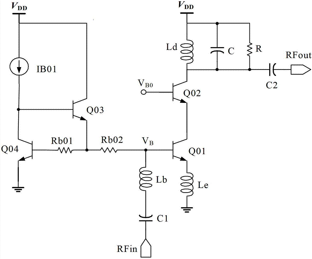
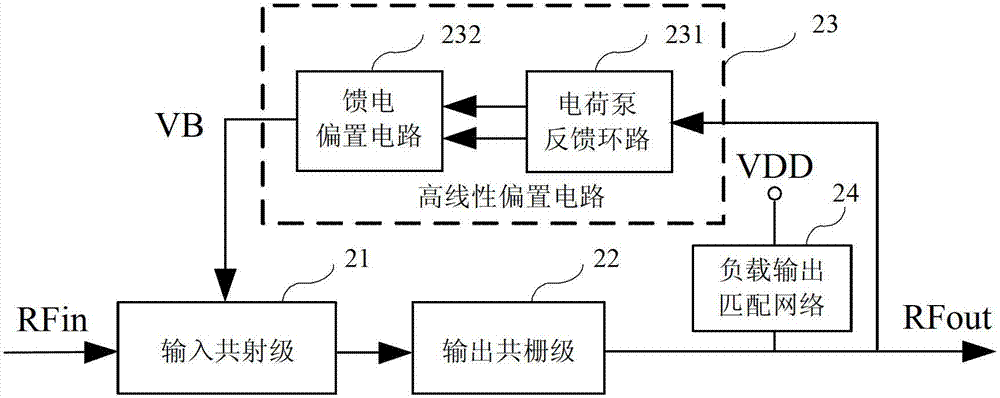
[0050] Figure 4a and Figure 4b The circuit diagrams of the high-linearity RF low-noise amplifiers of the first embodiment and the second embodiment of the present invention are given. As shown in FIG. 4 , the high linearity radio frequency low noise amplifier mainly includes four parts: an input cascode stage 41 , an output cascode stage 42 , a load output matching network 43 and a high linearity bias circuit 44 . The input common emitter stage 41 converts the radio frequency input voltage signal into a current signal while providing low noise performance; the output common gate stage 42 adds the current signal output by the input common emitter stage 41 to the load output matching network 43, while outputting impedance matching , the resonant load obtains high gain, and generates an output voltage signal amplified by low noise at the output terminal RFout. The high linearity bias circuit 44 provides a constant bias voltage V for the input tube of the input common emitter ...

no. 2 example

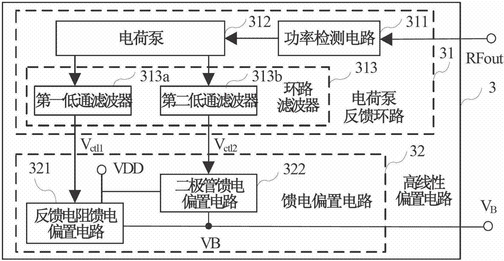
[0062] Figure 4b The second embodiment circuit shown with Figure 4a The circuit of the first embodiment shown is basically the same, the difference between the two embodiments is that the diode feed bias circuit is composed of the second current source IB2, the third MOS transistor M3, the fourth MOS transistor M4 and the fifth MOS transistor Composed of M5, the third MOS transistor M3, the fourth MOS transistor M4 and the fifth MOS transistor M5 are diode-connected structures, that is, their gates and drains are short-circuited. The source of the fourth MOS transistor M4 is connected in series with the drain of the fifth MOS transistor M5, and the source of the fifth MOS transistor M5 is grounded.

[0063] The output end of the second current source IB2 is connected to the drain of the third MOS transistor M3 and the drain of the fourth MOS transistor M4, and the source of the fifth MOS transistor M5 is grounded; the output end of the diode feed bias circuit 462 is the thi...


PUM


Abstract

The invention provides a radio frequency low amplifier with high linearity. The amplifier comprises an input common emitter gate, an output common bar gate, a load output matching network and a biasing circuit, wherein the biasing circuit comprises a charge pump feedback loop and a high linearity biasing circuit of a feed biasing circuit. The input common-emitter grade and the output common bar gate refer to hetero junction bipolar transistor (HBT)-metal-oxide-semiconductor field effect transistor (MOSFET) tubular structure in order to improve linearity and obtain good low noise performance. The biasing end of an input tube of the input common emitter gate is connected with the high linearity biasing circuit, the feed biasing circuit is a combination structure of a resistance feed biasing circuit and a diode feed biasing circuit. When a strong signal is inputted, the input tube provides a base current to compensate the decrease of voltage of a base electrode and an emitting electrode of the input tube. When a small signal is input, the charge pump feedback loop makes no contribution, the feed biasing circuit is in a regular work so that a constant biasing voltage is obtained, and therefore the linearity of the low noise amplifier is improved remarkably. The amplifier has the advantages of guaranteeing the performance of the low noise performance, improving greatly the linearity and achieving monolithic integration.

Description

[0001] technical field [0002] The invention belongs to the technical field of wireless radio frequency communication integrated circuits, and relates to a low noise amplifier with low noise and high linearity, in particular to a radio frequency low noise amplifier with high linearity, which is applied to a radio frequency front-end chip of a wireless communication receiver system. Background technique [0003] In the wireless communication radio frequency receiving chip, the low noise amplifier is located at the front end and is the key module of the entire radio frequency front end. Its noise figure directly determines the lower limit of the noise figure of the entire receiver and affects the receiving sensitivity of the system. The low-noise amplifier should amplify the radio frequency signal on the premise of generating noise as low as possible, so as to reduce the influence of the noise generated by the modules at all levels behind on the signal. The low noise ampl...

Claims


Application Information

Patent Timeline
IPC IPC(8): H03F3/189H03F1/32H03F1/26
Inventor 项勇周仁杰罗彦彬甘业兵钱敏马成炎
Owner JIAXING LIANXING MICROELECTRONICS
Why Eureka
Try Eureka