Method for improving compactness of 3D (three dimensional) printing metal part by adopting second laser beam

A technology of 3D printing and metal parts, applied in the direction of metal material coating process, coating, etc., can solve problems such as gaps and non-functional devices, and achieve the effects of uniform distribution, thorough remelting, and improved compactness

Inactive Publication Date: 2013-06-26
张翀昊
View PDF11 Cites 53 Cited by
  • Summary
  • Abstract
  • Description
  • Claims
  • Application Information

AI Technical Summary

Problems solved by technology

Since the material is the fundamental factor that determines the performance of the formed part, the limitations of the material lead to the fact that most of the devices made by the rapid prototyping machine are samples that can only be used for shape observation, not real functional devices, especially if the 3D printing technol

Method used


Image

  • Method for improving compactness of 3D (three dimensional) printing metal part by adopting second laser beam

Examples


Embodiment 1

[0024] A method for improving the densification of 3D printed metal parts using a second laser beam, comprising:

[0025] a. Pre-treat the printing base and the printing base; the pre-treatment includes removing oil stains or other impurities on the surface of the base and the printing base, wherein the removal of oil can be done by heating or using an organic cleaner to remove oil, The printing base is used as the basis for layer-by-layer superimposition of printing layers. The printing layer of the first layer is printed on the printing base, and finally the metal parts are formed on the printing base.

[0026] b.Using the first laser and alloy powder to run on the printing base plate according to the preset trajectory, relying on multi-channel overlapping and layer-by-layer superposition for 3D printing, and inert gas protection for the workpiece surface and powder flow field during the printing process Generally, the thickness of each layer of printing layer is controlled ...

Embodiment 2

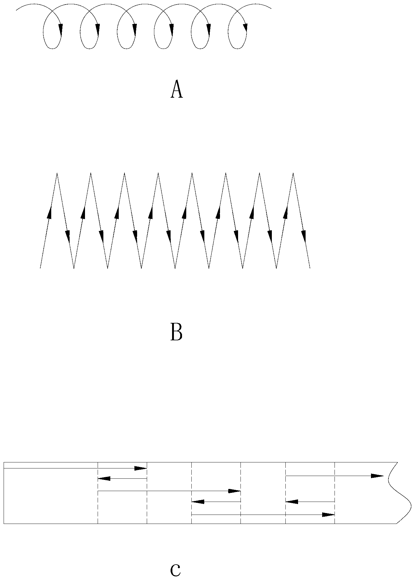
[0035] The steps in this embodiment are the same as in Embodiment 1, except that the specific process parameters are slightly different. In this embodiment, the first laser is a carbon dioxide laser, and the first laser is operated in a multi-pass overlapping mode. The alloy powder The powder feeding direction is coaxial with the first laser beam, the laser wavelength of the first laser is 10.6μm, the output power is 5000W, the running speed is 2-15mm / s, and the single-track width is 2-6mm. The second laser is also a carbon dioxide laser. Its operating speed and laser wavelength are the same as those of the first laser. The distance between the center of the spot of the second laser and the center of the spot of the first laser is 30mm. The intersecting angle between the layers is 85°, and the advancing method of the second laser is selected as a broken line, such as figure 1 As shown in Figure B, the lines in this figure schematically represent the running line of the center ...

Embodiment 3

[0041] This embodiment is basically the same as Embodiment 1, the distance between the center of the spot of the second laser and the center of the spot of the first laser is 40 mm, the angle of intersection between the second laser and the printing layer is 82°, and the stacking is also It is determined by the operation of the spot center of the second laser beam irradiated on the printing layer, such as figure 1 As shown in Figure C in Figure C, the direction of the arrow in Figure C schematically represents the running route of the center of the second laser spot. Its front and back directions are determined according to the forward direction of the first laser beam. The alloy powder used in this embodiment is a cobalt-based alloy powder, and its composition is by weight percentage: 25%WC, 1%C, 4%CaF2, 6%SiN4, 20%Cr, 4%B, 1%V, 3 %Si, 15%Mo, 1.5%Mn, the balance is Co, and the above materials are all 100-200 mesh powder.

[0042] It can be seen from the above that this meth...


PUM


Abstract

The invention discloses a method for improving the compactness of a 3D (three dimensional) printing metal part by adopting a second laser beam. The method comprises the following steps of: (a) pretreating a printing base and a printing baseplate; (b) carrying out 3D printing on the printing baseplate by using a first laser beam and alloy powder according to a preset moving trajectory by the way of lap joint step by step and superimposing layer by layer, protecting the surface of a workpiece and the flow field of the alloy powder by an inert gas in the process of printing, and melting the alloy powder by using the first laser beam to form a printing layer; (c) remelting the printing layer which is obtained by carrying out 3D printing by using the following second laser beam, wherein the second laser beam advances spirally or zigzag or telescopes back and forth according to the moving trajectory of the first laser beam; and (d) post-processing the metal part. Because the printing layer is remolten synchronously by adopting the second laser beam, the defects of holes, air pockets, thermal cracks and interface cracks generated in the process of carrying out 3D printing can be reduced, and the compactness of a metal tool can be improved.

Description

technical field [0001] The invention relates to a 3D printing method for metal parts, in particular to a method for improving the compactness of 3D printed metal parts by using a second laser beam. Background technique [0002] 3D printing technology is an emerging forming method, the core of which is to convert the complex 3D shape of the workpiece to be formed into a combination of simple 2D sections through slicing, so it is not necessary to use traditional processing machines and molds. The computer-aided design model, on the computer-controlled rapid prototyping machine, deposits materials layer by layer along the height direction, forming a series of 2D cross-sectional thin sheets of the workpiece, and bonding the sheets to each other, and finally stacking them into a three-dimensional workpiece . The current main 3D printing methods include laser curing method, laser sintering method, laser paper cutting method, three-dimensional printing method and melt extrusion me...

Claims


Application Information

Patent Timeline
IPC IPC(8): C23C24/10B22F3/105B22F7/04
Inventor 张翀昊柳岸敏杨健邵国锋
Owner 张翀昊
Why Eureka
Try Eureka