Sand and water separation system and method

A sand-water separation and dewatering screen technology, which is applied in separation methods, filtration separation, chemical instruments and methods, etc., can solve problems such as waste, high power consumption, and large floor space

Active Publication Date: 2013-07-24
ZHEJIANG SHUANGJIN MACHINERY HLDG
View PDF4 Cites 8 Cited by
  • Summary
  • Abstract
  • Description
  • Claims
  • Application Information

AI Technical Summary

Problems solved by technology

Its shortcomings: first, large investment, large floor area, and high power consumption; second, low efficiency of sand-water separation; third, fixed sand-water separation system, which cannot be moved; fourth, it remains on the screen surface of the dewatering screen The coarse sand cannot naturally form a sand wall on the dewatering screen plane, so it cannot achieve continuous dehydration during operation
[0003] 2. In the context of cobblestones and other water-based extraction of machine-made sand and raw sand, the current market basically adopts: drum type sand washing machine, winch cage type sand twisting machine and wheel type sand lifting machine and some areas. The bucket-lift sand lifter is used to extract coarse sand. When the above methods are used alone, there are serious tailings.
Not only does the water content of the finished products prepared by the above-mentioned equipment remain high, but the gradation of the produced machine-made sand and raw sand products is unreasonable, and the medium and fine sand run out seriously, and the finished products with qualified grading cannot be obtained, which has caused Serious waste, but also secondary pollution caused by the environment, etc. For this reason, in order to achieve the gradation of qualified machine-made sand and original sand, and to prevent secondary pollution, the manufacturer has to be equipped with a dehydrator and a tailing There are many auxiliary equipment such as sand recovery devices, which have caused many problems such as excessive investment in equipment in the system, high unit price, large floor area, and excessive power consumption.

Method used


Image

  • Sand and water separation system and method
  • Sand and water separation system and method
  • Sand and water separation system and method

Examples


Embodiment 1

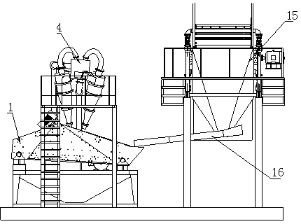
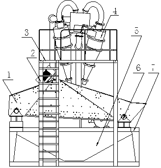
[0015] Embodiment 1: with reference to attached Figure 1-6 . A sand-water separation system, including a dewatering screen, a cyclone (one set) or a cyclone group and vibration screening equipment, the vibration screening equipment 15 and the wide water storage type dehydration screen 1 are integrated on the base, and the cyclone Or the cyclone group 4 is integrated on the top of the wide water storage dewatering screen 1 through the support frame, and the sand-water mixture is conveyed between the vibration screening equipment 15 and the wide water storage dewatering screen 1 through the quicksand tank 16, and the wide water storage type The dewatering screen 1 is positioned on the frame 7 through the shock absorber 6, and the shock absorber 6 is a rubber-metal helical composite spring, or a hydraulic shock absorber. When the rubber-metal helical composite spring is used as the shock absorber, the lower port of the rubber-metal helical composite spring is plugged with the b...

Embodiment 2

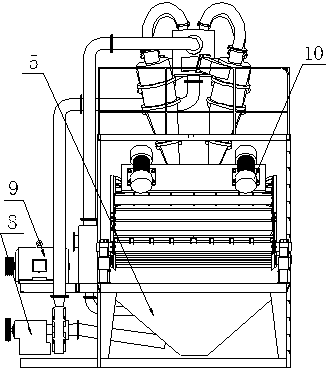
[0020] Embodiment 2: On the basis of Embodiment 1, when the flow rate of sand water treated by the wide-width water storage dewatering screen 1 per hour is greater than 300 cubic meters of water, the bottom plate, lower end sieve plate and side sieve plates of the frame are all screen holes plate.

Embodiment 3

[0021] Embodiment 3: On the basis of Embodiment 1, a sand-water separation method of a sand-water separation system, the sediment-water mixture screened by the vibrating screening device 15 passes through the quicksand tank 16 to the wide water storage type dewatering screen 1, Since the inclination angle between the bottom plate of the wide water storage dewatering screen 15 and the horizontal plane is greater than 3 degrees, and the vibration of the wide water storage dewatering screen 1 is driven by an exciting motor or a camshaft drive mechanism, the wide water storage dewatering screen is forced to The vibration trajectory of the screen 1 forms a front-to-back straight-line walking up and down motion, so when the sand-water mixture washed down from the vibrating screening equipment 15 is washed through the wide-width water storage dewatering screen 15 to the outwardly inclined open facade screen hole When the plate 13 is on the surface, the outwardly inclined open facade s...


PUM


Abstract

The invention relates to a sand and water separation system and method, can effectively separate mud, water and sand in a mud, sand and water mixture, and also can dehydrate the sand and the water efficiently. The sand and water separation system comprises a dehydration screen, a rotational flow device or a rotational flow device group and a vibrating and screening device; the vibrating and screening device and a wide-amplitude water-storage-type dehydration screen are integrated on a base; the rotational flow device or the rotational flow device group is integrated above the wide-amplitude water-storage-type dehydration screen through a support frame; a sand and water mixture is conveyed between the vibrating and screening device and the wide-amplitude water-storage-type dehydration screen through a sand flowing groove; the wide-amplitude water-storage-type dehydration screen is positioned on a rack through a shock absorber; the wide-amplitude water-storage-type dehydration screen is driven by a shock excitation motor or a cam wheel driving mechanism; a wide-amplitude water storage groove is positioned below the wide-amplitude water-storage-type dehydration screen; a material inlet of the rotational flow device or the rotational flow device group is communicated with an outlet of a slurry pump at the side part of the rack through a conveying pipeline; and the motor drives the slurry pump through a belt driving mechanism.

Description

technical field [0001] The invention relates to a sand-water separation system and a sand-water separation method capable of effectively separating mud, water and sand in a silt-water mixture and efficiently dehydrating the sand and water, belonging to the field of sand-water separation system manufacturing. Background technique [0002] 1. CN201524486U, name "sand water separation and recovery system", which includes mud and sand water classification equipment, sand dewatering equipment and mud dehydration equipment; the mud and sand water classification equipment includes a working cylinder, a feeding pipe, an overflow pipe, and a sand outlet , the feed pipe and the overflow pipe are fixedly connected around the working cylinder, the grit chamber is arranged at the lower end of the working cylinder, and the working cylinder is a hollow cylinder connected with a An inverted cone communicating with the cylinder; the sand dewatering equipment includes a screen box, a vibrator...

Claims


Application Information

Patent Timeline
Patent Type & Authority Applications(China)
IPC IPC(8): B01D36/04
CPCB01D36/04B01D33/0346
Inventor 黄建伟胡建明蒋刚
Owner ZHEJIANG SHUANGJIN MACHINERY HLDG
Why Eureka
Try Eureka