Testing device for catalytic coefficient of thermal shielding material and method for testing catalytic coefficient of thermal shielding material by utilizing device

A technology of thermal protection material and catalytic coefficient, applied in material excitation analysis, thermal excitation analysis, etc., can solve the problems of complex experimental process and long experimental period, and achieve the effect of accurate calculation and simple test method.

Inactive Publication Date: 2013-08-07
HARBIN INST OF TECH
View PDF1 Cites 10 Cited by
  • Summary
  • Abstract
  • Description
  • Claims
  • Application Information

AI Technical Summary

Problems solved by technology

[0006] The purpose of the present invention is to solve the problems of long experimental period and complicated experimental process in detecting the catalytic properties of thermal protection materials by using arc heaters, and provide a device for testing the catalytic coefficient of thermal protection materials and a method for testing the catalytic coefficient of thermal protection materials by using the device method

Method used


Image

  • Testing device for catalytic coefficient of thermal shielding material and method for testing catalytic coefficient of thermal shielding material by utilizing device
  • Testing device for catalytic coefficient of thermal shielding material and method for testing catalytic coefficient of thermal shielding material by utilizing device
  • Testing device for catalytic coefficient of thermal shielding material and method for testing catalytic coefficient of thermal shielding material by utilizing device

Examples


specific Embodiment approach 1

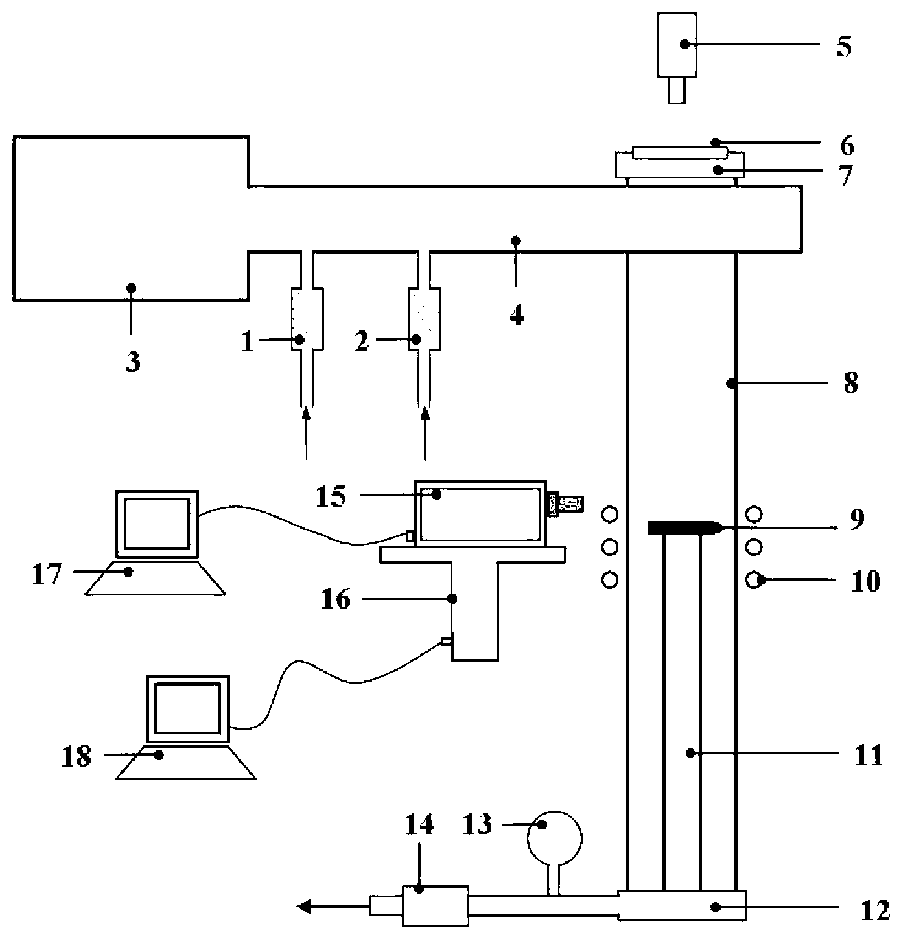
[0017] Specific implementation mode 1: Combination figure 1 , This embodiment is a thermal protection material catalytic coefficient testing device, including a carrier gas flow meter 1, an inert gas flow meter 2, a microwave power source 3, a waveguide 4, a double color pyrometer 5, calcium fluoride glass 6, a A mechanical seal part 7, a quartz tube 8, an electromagnetic induction heating coil 10, a zirconia bracket 11, a second mechanical seal part 12, a pressure gauge 13, a vacuum pump 14, a spectrometer 15, a mechanical lift table 16, a spectrometer signal receiving computer 17 and machinery Lifting platform control computer 18; the carrier gas flowmeter 1 and the inert gas flowmeter 2 are respectively connected to the waveguide 4, the microwave power source 3 and the waveguide 4 are connected together to form a plasma generation system, the quartz tube 8 and the waveguide 4 is connected, the calcium fluoride glass 6 is sealed and fixed on the upper part of the quartz tube ...

specific Embodiment approach 2

[0019] Specific implementation manner two: combination figure 1 This embodiment is a method for testing the catalytic coefficient of a thermal protective material by using a thermal protective material catalytic coefficient test device, which is specifically completed as follows:

[0020] 1. First, put the sample 9 to be tested on the zirconia support 11 of the thermal protection material catalytic coefficient test device, and then charge the carrier gas into the waveguide 4 through the carrier gas flow meter 1 at a flow rate of 10mL / min~300mL / min At the same time, fill the waveguide 4 with inert gas through the inert gas flowmeter 2 at a flow rate of 1mL / min~50mL / min, and control the flow rate of the inert gas to the carrier gas flow rate to 1:(4~99), control the waveguide 4 The internal gas pressure is 1Pa~1000Pa; 2. Start the electromagnetic induction heating coil 10 through the quartz tube 8 to heat the sample 9 to be tested, and heat the sample 9 to be tested from room tempe...

specific Embodiment approach 3

[0021] Embodiment 3: The difference between this embodiment and Embodiment 2 is that the carrier gas described in step 1 is oxygen, nitrogen or air. Others are the same as the second embodiment.


PUM


Abstract

The invention discloses a testing device for a catalytic coefficient of a thermal shielding material and a method for testing the catalytic coefficient of the thermal shielding material by utilizing the device, relating to the testing device for the catalytic coefficient of the thermal shielding material and a testing method for the catalytic coefficient of the thermal shielding material. The invention aims to solve the problems of long experimental periods and complex experimental processes when an electro-arc heater is used for detecting catalytic characteristics of the thermal shielding material. The testing device comprises a carrier gas flow gauge, an inert gas flow gauge, a microwave power source, a wave guide, double-colorimetric pyrometer, calcium fluoride glass, a first mechanical seal component, a quartz tube, electromagnetic induction heating coils, a zirconium oxide bracket, a second mechanical seal component, a pressure gage, a vacuum pump, a spectrograph, a mechanical lifting platform, a spectrograph signal receiving computer and a mechanical lifting platform control computer. The method comprises the steps of: (1) carrying aeration and pressure control; (2) heating; (3) starting the microwave power source; (4) scanning a recording result; and (5) measuring and calculating according to a diffusion controlling equation. The testing device and the method are mainly used for measuring and calculating the catalytic coefficient of the thermal shielding material.

Description

Technical field [0001] The invention relates to a thermal protection material catalytic coefficient testing device and a thermal protection material catalytic coefficient testing method. Background technique [0002] The process of breaking molecules into atoms and rearranging and combining atoms to form new substances is called a chemical reaction. The reaction is often accompanied by phenomena such as luminescence, heat generation, discoloration, and precipitation. The speed of a chemical reaction is usually measured by the chemical reaction rate, which is expressed by the amount of reactant or product in a unit time. The rates of different chemical reactions vary greatly. For example, the explosive reaction is almost instantaneous, while the reaction rate of elemental gold in the air and oxygen is very slow, almost no reaction. Therefore, in order to speed up or slow down the chemical reaction rate, some chemical reaction processes can be carried out as expected. Add a cert...

Claims


Application Information

Patent Timeline
Patent Type & Authority Applications(China)
IPC IPC(8): G01N21/71
Inventor 张幸红李宁韩文波胡平王鹏洪长青
Owner HARBIN INST OF TECH
Why Eureka
Try Eureka