
Thin film type optical collimator on basis of surface plasmon polaritons

A surface plasmon and light collimation technology, applied in optics, instruments, optical components, etc., can solve problems such as increased design costs and complex device structures, and achieve the effects of improving divergence angle, small size, and expanding beam width

Inactive Publication Date: 2013-08-07
TAIYUAN UNIV OF TECH
View PDF10 Cites 8 Cited by
  • Summary
  • Abstract
  • Description
  • Claims
  • Application Information

AI Technical Summary

Problems solved by technology

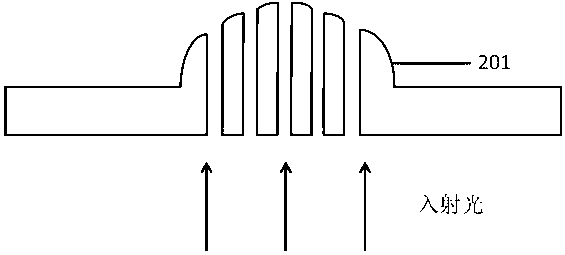
However, the structure of this device is more complex and requires the use of overlay and other manufacturing processes to obtain
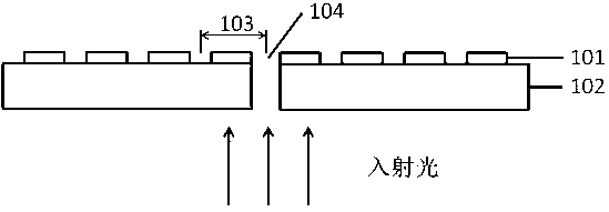
[0010] In addition, the surface wave emitted from the metal via and the surface wave emitted from the exit grating have different distributions and intensities. In order to make the two form constructive interference to meet the wave mismatch condition, it is necessary to carefully adjust the distance from the exit surface to the via hole. The distance between the center of the grating groove and the center of the via hole (104), which in turn brings about an increase in design cost

Method used


Image

  • Thin film type optical collimator on basis of surface plasmon polaritons
  • Thin film type optical collimator on basis of surface plasmon polaritons
  • Thin film type optical collimator on basis of surface plasmon polaritons

Examples


Embodiment 1

[0048] The wavelength of the Gaussian light source is taken as 595 nm, the metal is taken as silver, and the medium is taken as molybdenum oxide. After analysis, we get:

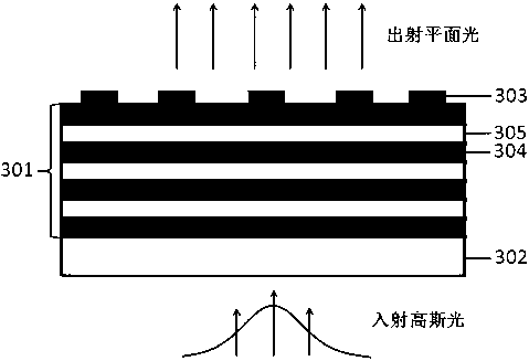
[0049] 1) When the ratio of the silver metal film 304 and the molybdenum oxide dielectric film 305 is 1:1.5 to 1:0.5, Gaussian light can obtain collimated light through the film light shaper; further, the silver metal film 304 and the molybdenum oxide dielectric film 305 The best effect is when the ratio is 1:1.2, that is, the transmittance is relatively high and the side lobes are relatively weak.

[0050] 2) When the thickness of the silver metal film 304 and the molybdenum oxide dielectric film 305 is 5-15 nm, Gaussian light can obtain collimated light through the film light shaper; further, the thickness of the silver metal film 304 and the molybdenum oxide dielectric film 305 are respectively Works best at 11 nm and 13.2 nm.

[0051] 3) When the total number of layers of the silver metal thin film 304...


PUM

PropertyMeasurementUnit
Thicknessaaaaaaaaaa
Depthaaaaaaaaaa

Abstract

The invention relates to a thin film type optical collimator on the basis of surface plasmon polaritons, which is formed by a substrate and a metal grating. The substrate is a glass substrate for bearing the metal grating; and the metal grating is formed by a metal medium alternate film and a metal surface grating structure, wherein the metal medium alternate film is obtained by alternately making a metal thin film and a medium thin film on the substrate by a vacuum hot dip coating technology or a magnetron sputtering technology and the metal surface grating structure is made on the metal medium alternate film by a two-beam interference exposure technology and a stripping technology. The structure changes Gaussian light into planar light by utilizing the metal medium alternate film for the first time and also has capacity of expanding the light beam width; the structure is compact, the size is small and the total thickness of a device is used as a wavelength magnitude; on the basis that the metal medium alternate film which adopts a simple preparation process and is low in cost supports the metal surface grating and conducts light, a metal film with a through hole, which is high in manufacturing cost, is avoided; and the thin film type optical collimator can be integrally made on the end faces of a semiconductor laser, a light emitting diode, an optical fiber or an optical fiber laser, and is used for improving an angle of divergence of a light beam and obtaining collimated light.

Description

technical field [0001] The invention relates to a light collimator in the field of photonics, more specifically, it is a kind of surface plasmon polaritons (Surface Plasmon Polaritons) excited by the composite structure of metal dielectric alternating film and metal surface grating to reduce the incident Gauss The divergence angle of the beam can be adjusted to obtain a thin-film light collimator for the outgoing beam that propagates close to the form of planar light. Background technique [0002] The function of the optical collimator is to change the light beam with a large divergence angle in the far field into a light beam with a small divergence angle, making it close to planar light. Wide range of applications. Currently, known light collimation devices are composed of traditional components such as lens groups or aspheric optical elements. For example, the published U.S. patents US4995709 (optical collimator), US7580192 (Collimation lens system for led) and Chinese ...

Claims


Application Information

Patent Timeline
IPC IPC(8): G02B27/30G02F1/01
Inventor 崔艳霞张收李国辉韩国华郝玉英张锋何赛灵
Owner TAIYUAN UNIV OF TECH
Learn More