
Technique method for filling spot welding stainless steel high-entropy alloy powder and for filling spot welding stainless steel with high-entropy alloy powder

A powder filling point and high-entropy alloy technology, which is applied in metal processing equipment, welding equipment, manufacturing tools, etc., can solve the problems of thin wafers that are not too conductive, increase equipment consumption, and reduce corrosion resistance, and achieve ideal Engineering practical significance, improvement of metallurgical behavior, effect of low cost

Inactive Publication Date: 2013-08-21
SHANGHAI UNIV OF ENG SCI
View PDF8 Cites 22 Cited by
  • Summary
  • Abstract
  • Description
  • Claims
  • Application Information

AI Technical Summary

Problems solved by technology

[0003] After searching the literature of the prior art, it is found that the patent 200510072511.5 uses the middle sheet ring to weld stainless steel, but the conductivity of the thin disk is not too strong, and the material of the thin disk is stainless steel homogeneous material, which has the effect of high current in resistance spot welding. It is easy to form ferrite under the environment, so the corrosion resistance decreases
Patent 201110028353.9 Changed the size of the electrode to improve the welding effect, but increased equipment consumption

Method used


Image

  • Technique method for filling spot welding stainless steel high-entropy alloy powder and for filling spot welding stainless steel with high-entropy alloy powder

Examples


Embodiment 1

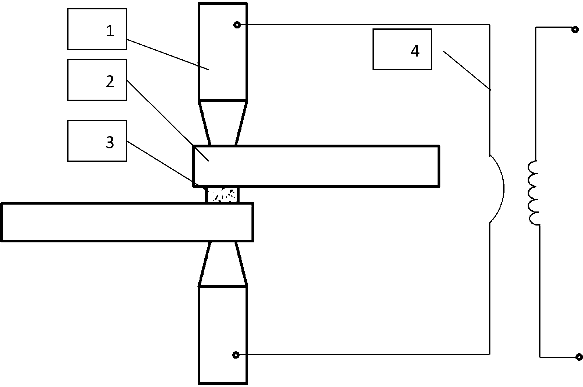
[0032] The clamping of the materials to be welded is as follows: figure 1 As shown, it is a single pulse current welding process. The 304 stainless steel workpiece 2 is the overlapping joint of two flat plates with a thickness of 0.8 mm. The high entropy alloy powder 200 mesh AlFeCuCoNiTiCr 0.1 After the medium is evenly mixed with acetone, it is evenly sprayed on the surface of the stainless steel workpiece 2 to be welded by a pressure sprayer to form a powder medium filling layer 3 . Set the four main welding parameters as follows: welding current I=12000A, electrode pressure F=1860N, welding current duration t2=1.3s. After the acetone in the powder filling layer is volatilized, the flat workpieces to be welded are overlapped and clamped between the upper and lower electrodes 1 . Aim the protective gas nozzle at the welding area, turn on the argon gas protection, and the gas flow rate is 3L / min. Apply electrode pressure to make the workpieces to be welded tightly. Maint...

Embodiment 2

[0034] The clamping of the materials to be welded is as follows: figure 1 As shown, it is a single pulse current welding process. The 304 stainless steel workpiece 2 is the overlapping joint of two flat plates with a thickness of 0.4 mm. The high entropy alloy powder 250 mesh AlFeCuCoNiTiCr 0.15 After the medium is evenly mixed with alcohol, it is evenly sprayed on the surface of the stainless steel workpiece 2 to be welded by a pressure sprayer to form a powder medium filling layer 3 . Set the four main welding parameters as follows: welding current I=10000A, electrode pressure F=1560N, welding current duration t2=1.3s. After the acetone in the powder filling layer is volatilized, the flat workpieces to be welded are overlapped and clamped between the upper and lower electrodes 1 . Aim the protective gas nozzle at the welding area, turn on the argon gas protection, and the gas flow rate is 4L / min. Apply electrode pressure to make the workpieces to be welded tightly. Main...

Embodiment 3

[0036] The clamping of the materials to be welded is as follows: figure 1 As shown, it is a single pulse current welding process. The 304 stainless steel workpiece 2 is the overlapping joint of two flat plate structures with a thickness of 1mm. The high entropy alloy powder 300 mesh AlFeCuCoNiTiCr 0.2 After the medium is evenly mixed with alcohol, it is evenly sprayed on the surface of the stainless steel workpiece 2 to be welded by a pressure sprayer to form a powder medium filling layer 3 . Set the four main welding parameters as follows: welding current I=13000A, electrode pressure F=1960N, welding current duration t2=1.3s. After the acetone in the powder filling layer is volatilized, the flat workpieces to be welded are overlapped and clamped between the upper and lower electrodes 1 . Aim the protective gas nozzle at the welding area, turn on the argon gas protection, and the gas flow rate is 4L / min. Apply electrode pressure to make the workpieces to be welded tightly....


PUM

PropertyMeasurementUnit
Thicknessaaaaaaaaaa
Thicknessaaaaaaaaaa
Thicknessaaaaaaaaaa

Abstract

The invention discloses a technique method for filling spot welding stainless steel high-entropy alloy powder and for filling spot welding stainless steel with high-entropy alloy powder. According to the technique method for filling the spot welding stainless steel high-entropy alloy powder and for filling the spot welding stainless steel with the high-entropy alloy powder, the high-entropy alloy powder is mainly composed of AlFeCuCoNiTiCrx, wherein the x is molar ratio of the Al to the Cr and is between 0 to 0.3, and the size of the powder is 100-300 meshes. When high-entropy alloy powder media are used as a filling layer, the contact resistance of a stainless steel material which are different to weld at the early welding stage is improved, resistance heat is used as a welding heat source, partial melting of the surface of the material to be welded is achieved under the protection of protective air and under the action of the resistance heat, an oxidation film can be broken under the impact effect of proper electrode pressure, refining of the high-entropy alloy powder media can be achieved on the interface of the material to be welded, a molten core and a single face-centered cubic tissue are formed on the interface, and then the strength and the corrosion resistance of a connector are improved. The technique method for filling the spot welding stainless steel high-entropy alloy powder and for filling the spot welding stainless steel with the high-entropy alloy powder has the advantages that welding can be achieved under the thermal compensation condition, the flexibility is strong, and ideal engineering significance is achieved.

Description

technical field [0001] The invention relates to the field of stainless steel welding, in particular to a high-entropy alloy powder for filling spot welding stainless steel and a process method for filling spot welding stainless steel with high-entropy alloy powder. Background technique [0002] As a corrosion-resistant material, stainless steel has always been valued by the industry, and the spot welding method is one of the main methods for stainless steel connection. At present, the research on stainless steel spot welding mainly includes argon arc welding, laser beam, electron beam, and friction stir spot welding, but the above-mentioned spot welding methods consume a lot of energy, have low production efficiency, and high equipment, maintenance and operation costs. Resistance spot welding stainless steel is an excellent choice, but the nugget formed after resistance welding stainless steel welding undergoes a phase change, which leads to corrosion during use, resulting i...

Claims


Application Information

Patent Timeline
IPC IPC(8): B23K11/11B23K11/02
Inventor 张培磊卢云龙闫华丁敏马凯褚振涛
Owner SHANGHAI UNIV OF ENG SCI
Learn More