
Biomass carbonization device

A biomass charcoal and chemical device technology, which is applied in the fields of biofuels, waste fuels, special forms of dry distillation, etc., can solve the problems of long carbonization time, environmental pollution, and low degree of automation.

Inactive Publication Date: 2013-08-21
HEFEI UNIV OF TECH
View PDF8 Cites 16 Cited by
  • Summary
  • Abstract
  • Description
  • Claims
  • Application Information

AI Technical Summary

Problems solved by technology

[0003] At present, the common biomass carbonization methods mainly include: carbonization kiln, intermittent carbonization method, closed boring tank carbonization method, and dry distillation method, but the carbonization time is long, the degree of automation is low, the quality of carbonized products is not high, the production environment is harsh, and the product quality heavily dependent on worker experience etc.
The relatively advanced Northeast honeycomb type and long charcoal kilns have a production cycle of 7 days; the new generation of mobile metal cabinet carbonization furnaces has relatively high efficiency. The carbon yield is about 25%, and the production cycle can be greatly shortened, but There are still problems of environmental pollution and low energy utilization
[0004] The biomass pyrolysis carbonization process is accompanied by the production of bio-oil and combustible gas. Distillates such as wood tar, wood vinegar, alcohols, ketones, aldehydes, and esters are important chemical raw materials. The operation data optimizes the product structure. At present, carbonization equipment ignores this beneficial part, and basically adopts emptying treatment, which pollutes the environment and wastes resources. These problems limit the healthy development of the biomass industry.

Method used


Image

  • Biomass carbonization device
  • Biomass carbonization device
  • Biomass carbonization device

Examples


Embodiment Construction

[0011] A biomass carbonization device of the present invention will be further described below in conjunction with the accompanying drawings.

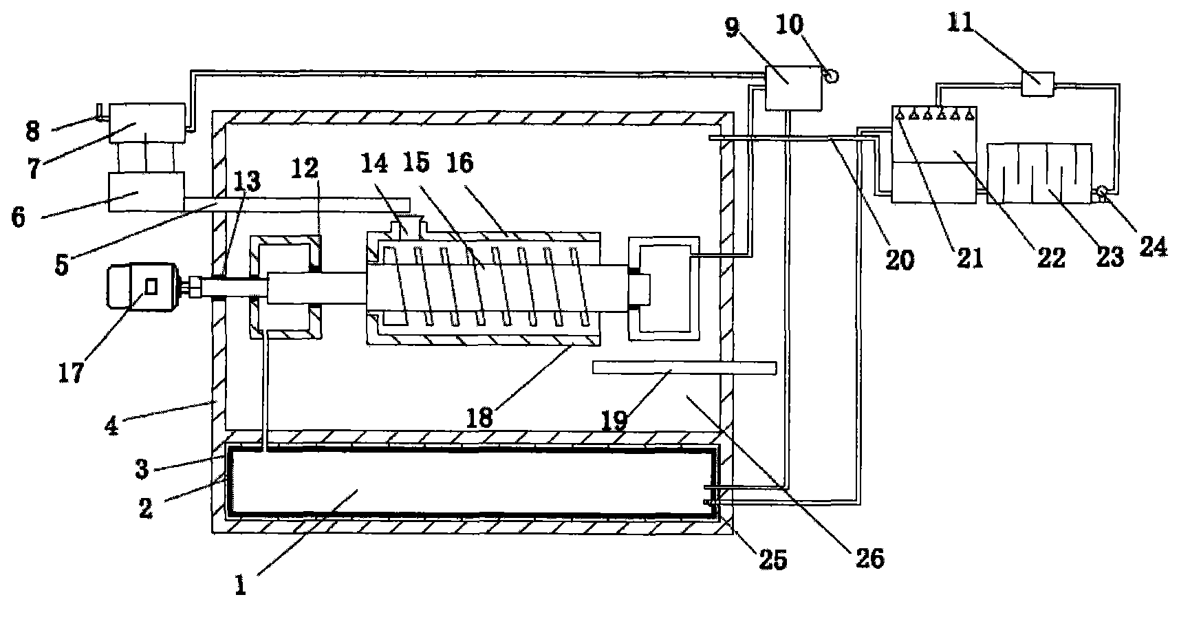
[0012] A biomass carbonization device of the present invention, the pyrolysis gas produced in the carbonization chamber 26 passes through the heat pipe air preheater 9, the pipeline 20, enters the combustion chamber 1 after spraying the settling chamber 22, and the hot air heated by the heat pipe air preheater 9 Combustion, the high-temperature flue gas produced is used as the main energy source of carbonization, so that the whole process basically does not require the addition of external energy to realize the orderly progress of the carbonization process. The high-temperature flue gas directly passes through the hollow screw shaft 15 with a heat storage body to heat the biomass. This design can not only heat the biomass, but the hollow screw shaft 15 with a heat storage body is driven by the motor 17 to rotate. It will also promote t...


PUM


Abstract

The invention relates to a biomass carbonization device, which mainly includes: a combustion chamber, a feed transmission belt, a biomass stock bin, a flash dryer, a flue gas outlet, a heat pipe air preheater, a hollow screw shaft with a heat accumulator, an upper sleeve, a lower sleeve, a biomass charcoal transmission belt, a pipeline, a spraying settling chamber, an oil separation pool, a carbonization chamber and auxiliary equipment. The device can realize comprehensive utilization of biomass carbonization products, and can realize co-production of biomass charcoal and bio-oil. At the same time, by adopting a circulating heat exchanger repeatedly, the emptied gas can have a low temperature, and the energy loss can be substantially reduced. The design of the hollow screw shaft with the heat accumulator realizes staged carbonization and combustion, thus improving the carbonization efficiency. The biomass carbonization device provided in the invention has the advantages of little pollution, high carbonization efficiency, good production environment, etc., and can achieve automated control. The biomass carbonization device is applicable to carbonization of straws, rice husks, sawdust, peanut shells and other biomass, and is suitable for rural families.

Description

Technical field: [0001] The invention relates to a device which directly utilizes pyrolysis gas in a carbonization process to provide heat to realize biomass carbonization. Background technique: [0002] At present, with the continuous reduction of primary energy sources such as coal, oil, and natural gas, human beings pay more attention to the development and utilization of various new energy sources. Biomass, as a renewable energy, is attracting widespread attention as a supplementary energy to fossil energy. The main ways to convert low-grade biomass energy into high-grade energy include gasification, liquefaction, carbonization and direct combustion technologies. Carbonization is a very potential conversion technology due to its high carbon yield and relatively mature technology. [0003] At present, the common biomass carbonization methods mainly include: carbonization kiln, intermittent carbonization method, closed boring tank carbonization method, and dry distillati...

Claims


Application Information

Patent Timeline
IPC IPC(8): C10B53/02C10B47/44C10B57/00
CPCY02E50/32Y02E50/14Y02E50/10Y02E50/30Y02P20/129
Inventor 邢献军李慧马培勇孙亚栋胡运龙李涛
Owner HEFEI UNIV OF TECH
Learn More