Method for preparing magnetic tunnel junction
A magnetic tunnel junction and magnetic technology, applied in the field of nanotechnology research and storage, can solve the problems of incompatibility with micromachining process, complicated process, difficult to obtain large-scale application, etc., and achieve good application potential, simple preparation process, and simple method. control effect
- Summary
- Abstract
- Description
- Claims
- Application Information
AI Technical Summary
Problems solved by technology
Method used
Image
Examples
Embodiment 1
[0040] In this embodiment, the preparation method of the magnetic tunnel junction is as follows.
[0041] Step 1. Preparation of "sandwich" structural unit:
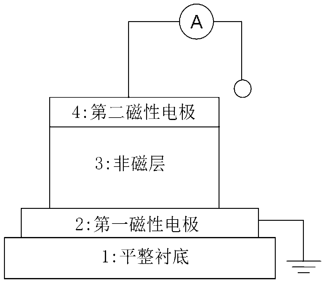
[0042] Using "sandwich" structural units, such as figure 1 As shown, in this structural unit, the first magnetic electrode 2 adopts iron with a thickness of about 100 nanometers, and the second magnetic electrode 4 adopts cobalt with a thickness of about 100 nanometers, located between the first magnetic electrode 2 and the second magnetic electrode 4, And the non-magnetic layer 3 in contact with the first magnetic electrode 2 and the second magnetic electrode 4 adopts zinc oxide with a thickness of about 100 nanometers;
[0043] The above-mentioned "sandwich" structural unit can be prepared sequentially on a flat substrate by using the existing coating process, and one of the preparation methods is as follows:
[0044] (1) First, sputter a layer of iron electrode as the first magnetic electrode 2 on the clean flat sub...
Embodiment 2
[0052] In this embodiment, the method for preparing the magnetic tunnel junction is basically the same as that of Embodiment 1, except that in step 1, the first magnetic electrode 2 of the "sandwich" structural unit is made of lanthanum strontium manganese oxide with a thickness of about 100 nanometers. compound, the nonmagnetic layer 3 uses zinc oxide with a thickness of about 200 nanometers, and the second magnetic electrode 4 uses cobalt with a thickness of about 100 nanometers.
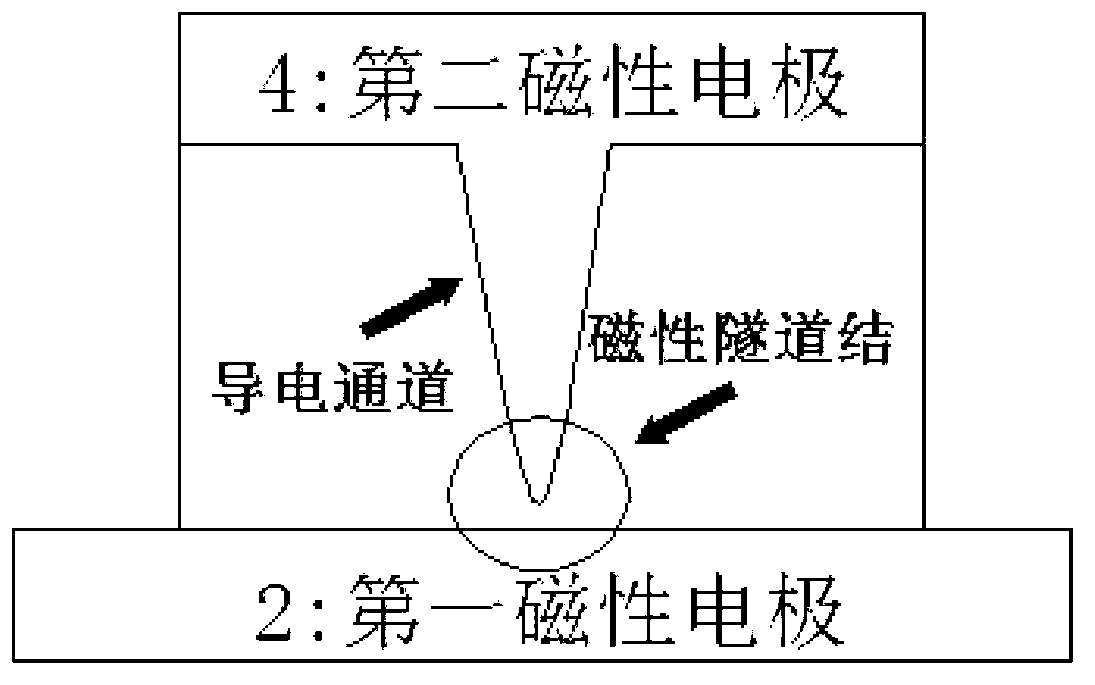
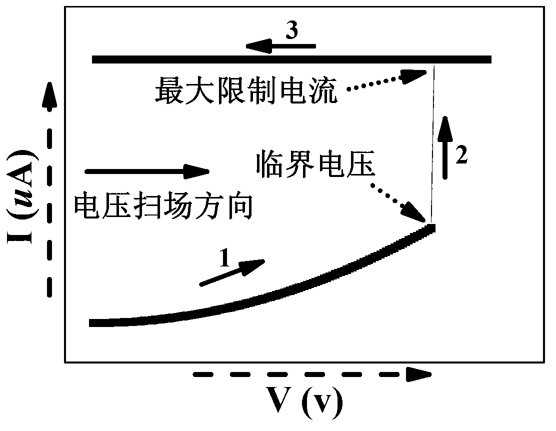
[0053] Similarly, a voltage is applied across the first magnetic electrode 2 and the second magnetic electrode 4 to ionize the magnetic atoms in the second magnetic electrode 2 into ions and move toward the first magnetic electrode 2 to form a conductive channel; increases, the distance from the conductive channel to the first magnetic electrode 2 decreases, the resistance of the "sandwich" structural unit becomes smaller, and the current increases; when the voltage increases to the critical voltag...
Embodiment 3
[0056] In this embodiment, the method for preparing the magnetic tunnel junction is basically the same as that of Embodiment 1, except that in step 1, the first magnetic electrode 2 of the "sandwich" structural unit is made of iron with a thickness of about 100 nanometers, which is non-magnetic. The layer 3 adopts bismuth ferrite with a thickness of about 150 nanometers, and the second magnetic electrode 4 adopts cobalt with a thickness of about 100 nanometers.
[0057] Similarly, a voltage is applied across the first magnetic electrode 2 and the second magnetic electrode 4 to ionize the magnetic atoms in the second magnetic electrode 2 into ions and move toward the first magnetic electrode 2 to form a conductive channel; increases, the distance from the conductive channel to the first magnetic electrode 2 decreases, the resistance of the "sandwich" structural unit becomes smaller, and the current increases; when the voltage increases to the critical voltage, the distance from ...
PUM
| Property | Measurement | Unit |
|---|---|---|
| Thickness | aaaaa | aaaaa |
| Diameter | aaaaa | aaaaa |
| Thickness | aaaaa | aaaaa |
Abstract
Description
Claims
Application Information
 - R&D
- Intellectual Property
- Life Sciences
- Materials
- Tech Scout
- Unparalleled Data Quality
- Higher Quality Content
- 60% Fewer Hallucinations
Browse by: Latest US Patents, China's latest patents, Technical Efficacy Thesaurus, Application Domain, Technology Topic, Popular Technical Reports.
© 2025 PatSnap. All rights reserved.Legal|Privacy policy|Modern Slavery Act Transparency Statement|Sitemap|About US| Contact US: help@patsnap.com


