Method for producing glass substrate for flat panel display

A flat panel display and glass substrate technology, applied in glass manufacturing equipment, glass forming, glass forming, etc.

Active Publication Date: 2013-08-28
AVANSTRATE INC
View PDF9 Cites 7 Cited by
  • Summary
  • Abstract
  • Description
  • Claims
  • Application Information

AI Technical Summary

Problems solved by technology

In addition, in glass substrates for TOS and TFT, suppression of thermal shrinkage is also a problem

Method used


Image

  • Method for producing glass substrate for flat panel display
  • Method for producing glass substrate for flat panel display
  • Method for producing glass substrate for flat panel display

Examples


Embodiment 1

[0120] (Production of sample glass)

[0121] Silicon dioxide, alumina, boron oxide, potassium carbonate, basic magnesium carbonate, calcium carbonate, strontium carbonate, tin dioxide, and ferric oxide were used as glass compositions shown in Table 1. , Blend glass raw material batch (hereinafter referred to as batch).

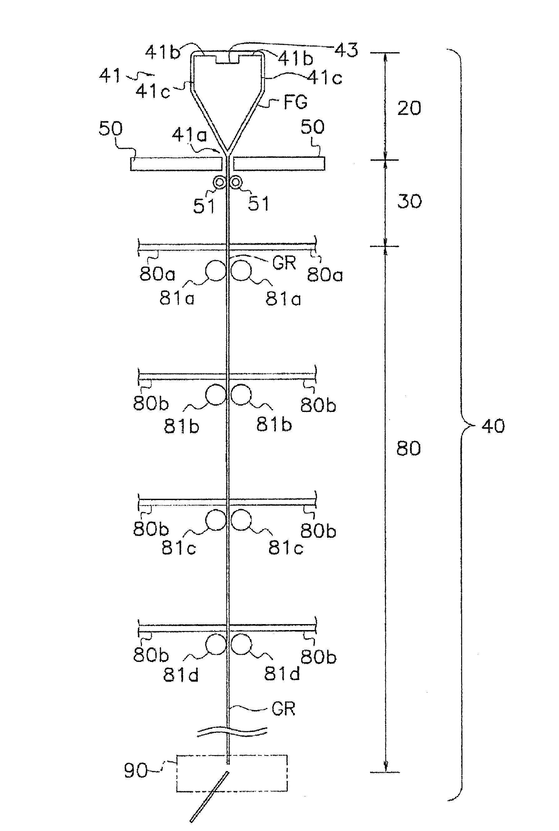
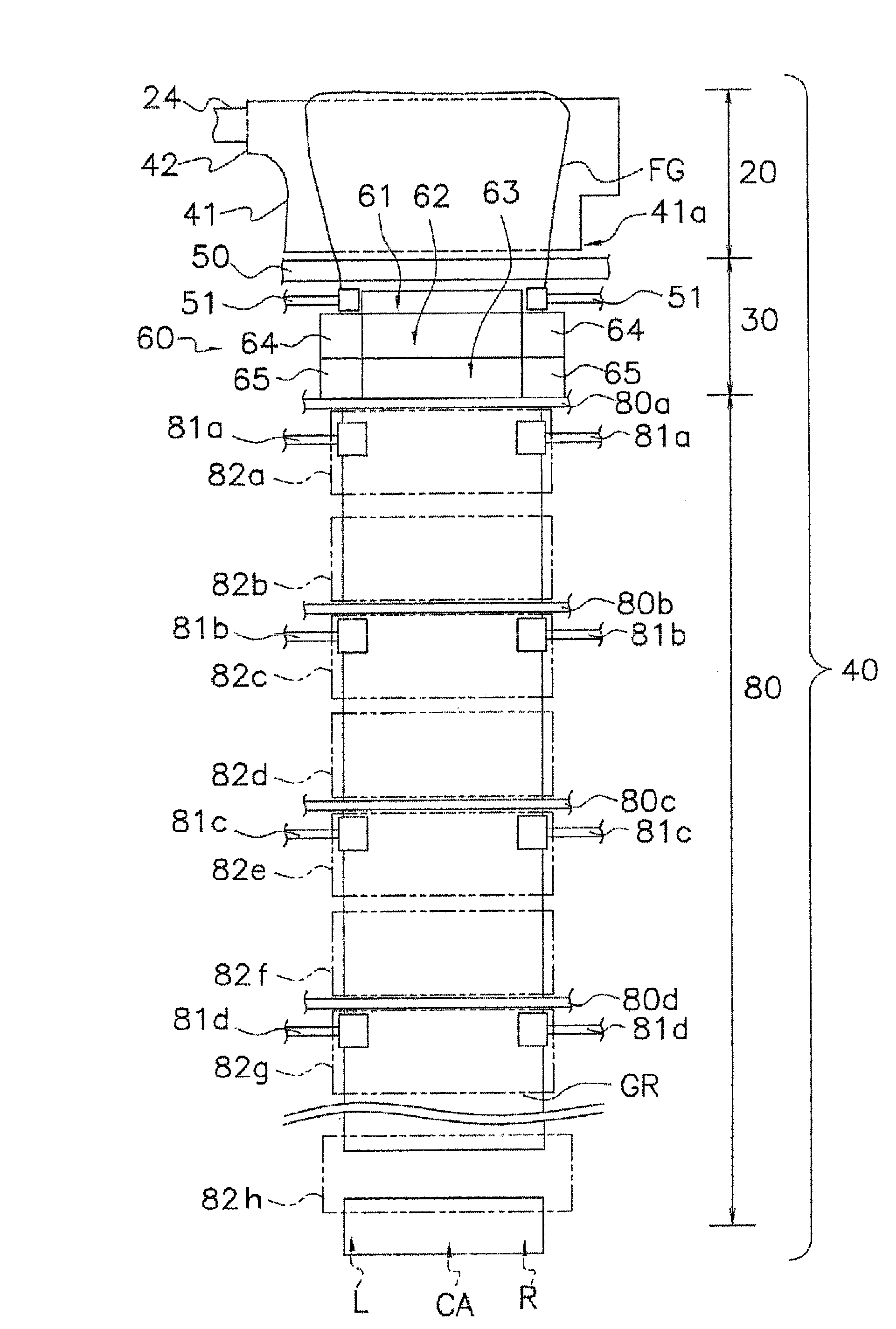
[0122] The above blended batch is melted at 1560-1640°C using a continuous melting device equipped with a refractory brick melting tank and a platinum alloy adjusting tank, clarified at 1620-1670°C and stirred at 1440-1530°C. use figure 1 and 2 The manufacturing device of the glass substrate shown is formed into a glass ribbon GR with a width of 1600 mm and a thickness of 0.7 mm by the overflow down-draw method, and annealed under prescribed conditions to obtain glass for liquid crystal displays (for organic EL displays) substrate. The prescribed annealing conditions are shown in Tables 2-6. Moreover, about each characteristic below, the glass substrate f...

Embodiment 2

[0155] Glass composition (mol%), devitrification temperature (°C), annealing point (°C), strain point (°C), average thermal expansion coefficient (×10 -7 ℃ -1 ), density (g / cm 3 ), Young's modulus (GPa), specific elastic modulus, melting temperature (°C), liquid viscosity (dPa·s), Tg (°C) and specific resistance (Ω·cm) are shown in Table 1. Moreover, the width|variety of glass ribbon GR is 1600 mm, and thickness is 0.7 mm.

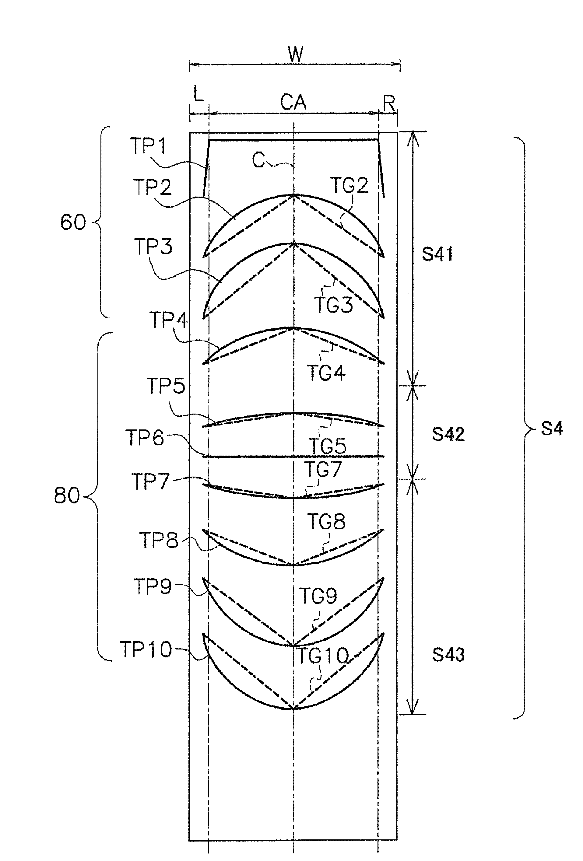
[0156]Tables 6-7 show the temperature change (degreeC) of glass ribbon GR in cooling process S4, and the actual measurement value of the time (second) required for temperature change, and the average cooling rate (degreeC / second) of center part C of glass ribbon GR. Tables 6 to 7 show values ​​when the average cooling rate (°C / sec) in S42 is 2.1 and 3.0, respectively. Furthermore, Table 8 shows the thermal contraction rate of the glass substrate manufactured when the average cooling rate (degreeC / second) in S42 was 2.1 and 3.0, respectively.

[0157] [...


PUM

PropertyMeasurementUnit
strain pointaaaaaaaaaa

Abstract

The present invention provides a method with which a glass substrate ideal for LTPSTFT in that it has a thermal contraction rate that allows for control of pixel pitch shift can be produced without compromising productivity using glass having a composition that is ideal for obtaining a light weight. The disclosed invention is a method for producing a glass substrate for a flat panel display. The production method comprises (1) a melting step for preparing and melting the starting materials such that the resulting glass substrate will have a combined SrO and BaO content of less than 8 mass% and a strain point of 675 C or less, (2) a forming step for forming glass ribbon from the molten glass by the overflow downdraw method, and (3) a cooling step for cooling the formed glass ribbon under the following condition (A), where (A) is an average rate of cooling from the annealing point to a temperature of (the strain point - 50 C) = less than 0.5 to 5.5 C / second.

Description

technical field [0001] The present invention relates to a glass substrate for a flat panel display. More specifically, the present invention relates to a method for manufacturing a glass substrate for a low-temperature polysilicon thin film transistor (hereinafter referred to as LTPS·TFT (Low-Temperature-Polycrystalline-Silicon Thin-Film-Transistor)) flat panel display. Furthermore, this invention relates to the manufacturing method of the glass substrate for flat panel displays of a transparent oxide semiconductor thin-film transistor (it describes hereafter as TOS·TFT (Transparent Oxide-Semiconductor Thin-Film-Transistor)). In more detail, this invention relates to the manufacturing method of the glass substrate used for the flat-panel display manufactured by forming LTPS or TOS on the surface of a substrate. In further detail, the present invention relates to a method of manufacturing a glass substrate for a flat panel display in which the above-mentioned flat panel displa...

Claims


Application Information

Patent Timeline
Patent Type & Authority Applications(China)
IPC IPC(8): C03B25/087C03B17/06C03C3/091C03C3/093G02F1/1333G02F1/1368G09F9/30H01L51/50H05B33/02
CPCC03B17/064C03B17/067C03B25/087C03C3/091G02F1/133302Y02P40/57C03B17/06G09F9/30
Inventor 小山昭浩苅谷浩幸
Owner AVANSTRATE INC
Why Eureka
Try Eureka