Sensing device of a fluorescent explosive detector

A sensing device and explosives technology, applied in the field of fluorescent explosives detection, can solve the problems of affecting the sensitivity of the instrument, inconvenient installation, fragile sensing film, etc., to ensure uniformity and real-time performance, and avoid contamination or damage , Improve the effect of sensitivity and accuracy

Active Publication Date: 2015-09-23
深圳砺剑防卫技术有限公司
View PDF10 Cites 0 Cited by
  • Summary
  • Abstract
  • Description
  • Claims
  • Application Information

AI Technical Summary

Problems solved by technology

[0003] The body detection technology of explosives is relatively mature, but the equipment is expensive, bulky, requires a fixed power supply, and is only suitable for the detection of tangible objects, so it is difficult to popularize
Most of the core components for micro-trace detection of explosives use photomultiplier tubes as photosensitive components, which are expensive, vulnerable to light when charged, and rarely have a complete and formed optical system, and the light sensitivity cannot reach Requirements, insufficient stability, prone to false positives or false negatives, etc. Therefore, most conventional methods are to place the chemical sensing film in the cuvette. Due to the large volume of the cuvette, if the chemical film sensor If it is placed in it, it is not only inconvenient to install but also unable to firmly fix the chemical film in the cuvette, the chemical fluorescence sensing film is easily contaminated, and it is easy to cause the sensor to deviate from its original position, the detection signal is unstable, etc., resulting in unstable detection and transmission. The unfavorable consequences such as the fragile sensitive film greatly affect the stability and sensitivity of the instrument, which greatly limits its popularization and application in actual production and life. In addition, placing the chemical sensing film in a cuvette cannot be completed. The deviceization of the entire chemical film is not conducive to the subsequent mass production, and it causes great inconvenience to the sensor replacement of the instrument, which is not conducive to the disassembly and assembly of the commercial sales and instrument sensor parts. At the same time, due to the relative space of the cuvette Larger, which affects the sensitivity of the instrument to a certain extent, the chemical sensing film is excited to generate a fluorescent signal, and the photoelectric signal generated by the photosensitive diode is submerged in the background noise of the system, which reduces the signal-to-noise ratio of the signal, which is not conducive to beneficial signal extraction

Method used


Image

  • Sensing device of a fluorescent explosive detector
  • Sensing device of a fluorescent explosive detector
  • Sensing device of a fluorescent explosive detector

Examples


Embodiment 1

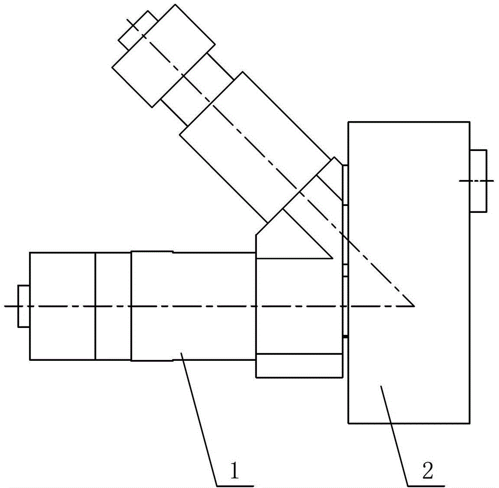
[0031] by figure 1 It can be seen that the sensing device of the fluorescent explosive detector of this embodiment is formed by connecting the air circuit assembly 1 and the optical assembly 2, and the optical assembly 2 is fixed to the air circuit assembly 1 by screws.

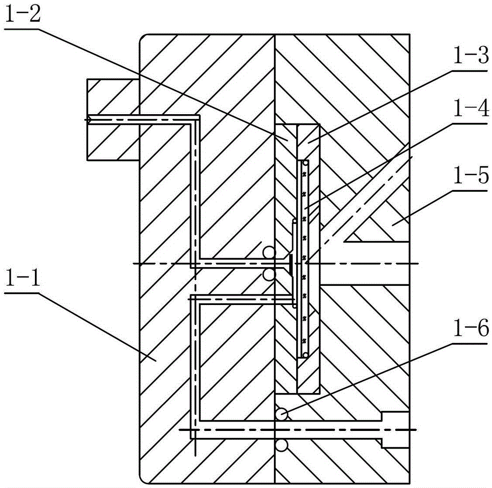
[0032] The above-mentioned air circuit assembly 1 is composed of the intake front cover 1-1, the sensor assembly front cover 1-2, the sensor assembly rear cover 1-3, the sensor film carrier 1-4, the light-transmitting rear cover 1-5, and the sealing ring 1-6 and baffle 1-7 connection structure, see figure 2 .

[0033] The air intake front cover 1-1 of this embodiment is made of aluminum alloy material. The air intake port is machined in the upper middle position of the air intake front cover 1-1, and the air intake front cover 1-1 is processed with the air intake port. The air inlet is connected to the air inlet channel, the upper air outlet channel and the lower air outlet channel are processed in sequence below...

Embodiment 2

[0045] In this embodiment, a first focusing lens 2-5 is installed in the first lens barrel 2-1 along the incident direction of the light source at a position 5 mm away from the emitting surface of the emitting light source 2-3, and the first focusing lens 2- 5 is a plano-convex lens with a radius of curvature of 15mm, the plane of the first focusing lens 2-5 is directly opposite to the light source, and the first narrow-band filter 2-6 is installed at a position where the center spacing of the convex side is 10mm.

[0046] A second filter 2-7 is installed in the second lens barrel 2-12 at a position 10 mm away from the sensor assembly along the emission direction of the fluorescence, and at a position 0.5 mm away from the center of the second filter 2-7 The condenser lens 2-8 is installed with a radius of curvature of 18mm, and the second focusing lens 2-9 is installed at a position 0.5mm away from the center of the condenser lens 2-8. The convex surface of the lens has a radius o...

Embodiment 3

[0051] In this embodiment, a first focusing lens 2-5 is installed in the first lens barrel 2-1 along the incident direction of the light source at a position 15 mm away from the emitting surface of the emitting light source 2-3. The first focusing lens 2- 5 is a plano-convex lens with a radius of curvature of 2mm. The plane of the first focusing lens 2-5 is directly opposite to the light source. The first narrow-band filter 2-6 is installed at the center of the convex side with a distance of 20mm. The bandwidth of filters 2-6 is 10nm.

[0052] A second filter 2-7 is installed at a position 10 mm away from the sensor assembly in the second lens barrel 2-12 along the emission direction of the fluorescence, and a second filter 2-7 is installed at a position 5 mm away from the center of the second filter 2-7 There is a condenser lens 2-8 with a radius of curvature of 2mm. A second focusing lens 2-9 is installed at a position 5mm away from the center of the condenser lens 2-8. The con...


PUM

PropertyMeasurementUnit
radiusaaaaaaaaaa
thicknessaaaaaaaaaa
thicknessaaaaaaaaaa

Abstract

The invention relates to a sensing device of a fluorescent exploder detector. The sensing device comprises a gas path assembly and an optical assembly, wherein the gas path assembly and the optical assembly are connected through a threaded fastener, a gas path and a light path are isolated, a light-emitting diode (LED) is adopted as an emitting light source, and a photosensitive diode is used as a photosignal transition element; the photosensitive diode is used as a photosensitive element through plane convex lenses and biconvex lenses which are arranged in an interval manner, a round groove channel is adopted to enable the entering gas to be uniformly distributed on the periphery of a sensing film reacting region, gas to be measured and the surface of the sensor reaction zone are uniformly contacted and reacted, and the gas is uniformly extracted. The sensing device provided by the invention can greatly extract a feebleness fluorescence signal, the extracted signal is stable, and the detective sensitivity and accuracy of an exploder are improved; a chemical film device is realized, problems that the chemical film is contaminated or damaged and the like are avoided, and further, disassembly and assembly are convenient, the maintenance is easy, and batch production is suitable.

Description

Technical field [0001] The invention belongs to the technical field of fluorescent explosive detection, and particularly relates to a sensing device of a fluorescent explosive detector in the micro-trace method for fluorescent detection of explosives. Background technique [0002] There are many types of explosives, and the packaging and hiding conditions are complex. These factors make it very difficult to accurately detect hidden explosives. Therefore, in the long-term detection practice, people have developed various explosive detection technologies. So far, explosive detection technology can be divided into two categories, namely: explosive volume detection technology and micro-trace detection technology. [0003] The volume detection technology of explosives has been relatively mature, but the equipment is expensive, bulky, requires a fixed power supply, and is only suitable for the detection of tangible objects, so it is difficult to popularize. Most of the core components ...

Claims


Application Information

Patent Timeline
Patent Type & Authority Patents(China)
IPC IPC(8): G01N21/64
Inventor 辛云宏董乐明陈彦涛刘太宏房喻
Owner 深圳砺剑防卫技术有限公司
Why Eureka
Try Eureka