Method and apparatus for improving hydrogen utilization rate of hydrogenation equipment

A utilization, hydrogen technology, applied in the field of hydrogen refining hydrocarbon oil

Active Publication Date: 2013-09-25
EAST CHINA UNIV OF SCI & TECH
View PDF9 Cites 12 Cited by
  • Summary
  • Abstract
  • Description
  • Claims
  • Application Information

AI Technical Summary

Problems solved by technology

But its disadvantages are: the addition of a high-temperature oil-gas separation system, and the large loss of hydrogen, and the concentration of circulating hydrogen is also slightly lower than that of the cold high-separation process, resulting in a slight increase in the pressure of the entire reaction system
[0005]Because the gas-liquid two phases of the hot high-pressure separator and the hot low-pressure separator in the current hydrogenation hot high-separation process usually adopt natural gravity settlement, as shown in the attached Figure 1-1, Figure 1-2, so some gases (mainly hydrogen) are inevitable The tiny bubbles exist in the liquid phase and are then sent to the follow-up device, resulting in the loss of part of the hydrogen; in addition, the thermal low-pressure separator adopts the traditional flash evaporation-gravity sedimentation separation method. The small contact surface leads to low flash evaporation efficiency, resulting in partial hydrogen loss; finally, because the pressure of the hot and low-pressure separator is designed at 1.2-3.0MPa (G), part of the hydrogen will be dissolved in the liquid phase under this partial pressure, which also causes Partial loss of hydrogen

Method used


Image

  • Method and apparatus for improving hydrogen utilization rate of hydrogenation equipment
  • Method and apparatus for improving hydrogen utilization rate of hydrogenation equipment
  • Method and apparatus for improving hydrogen utilization rate of hydrogenation equipment

Examples


Embodiment 1

[0043] A petrochemical hydrogenation unit adopts a thermal high-separation process, and the feed parameters of the thermal high-pressure separator are as follows:

[0044] name unit Material name: Hydrogen, oil gas, oil, H 2 S, NH3 total flow 433290 kg / h gas phase 81520 kg / h oil phase 351770 kg / h water box kg / h Operating Temperature - Max / Normal / Minimum / 210 / ℃ Operating Pressure - Max / Normal / Minimum 8.4 / 8.3 / MPa(g) Vacuum or Negative Pressure - Max / Min full vacuum MPa(abs) Medium density - at operating temperature gas phase 18.3969 kg / m 3 oil phase 733.4492 kg / m 3

[0045] Note: At the beginning of operation: the concentration of H2 in the gas phase is 73.8946% (v), the concentration of H2S is 1.8413% (v), and the concentration of H2S in the liquid phase is 0.177% (wt); at the end of operation: the concentration of H2 in the gas phase is 73.7534% (v) , the H2S c...

Embodiment 2

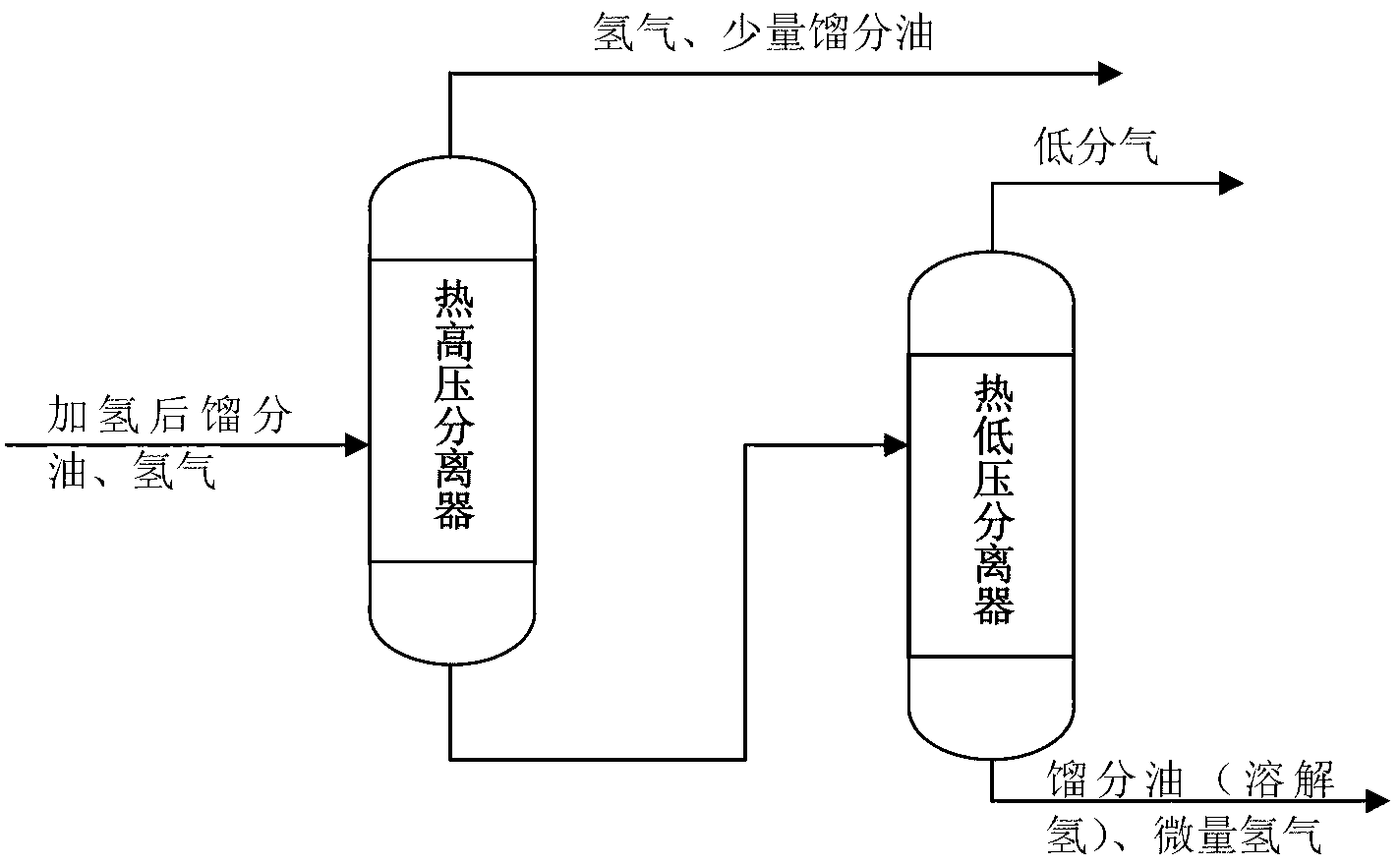
[0054] see Figure 4 , is the second embodiment of the present invention. What is different from the first embodiment is that the present embodiment is further connected in series with a second thermal low-pressure separator 3 of the same structure through a heat exchanger at the gas phase outlet 2-6 of the hot low-pressure separator 2, so as to separate the two gas phases at the hot low-pressure separator. After the outlet, heat exchange is performed on the low fraction gas, part of the hydrocarbons become liquid phase, and then pass through the second hot low pressure separator 3 to further purify the hydrogen contained in the low fraction gas. Compared with Example 1, this process further purifies the hydrogen, which is more conducive to the recovery and utilization of hydrogen.

[0055] The centrifugal degassing core tube in the above embodiment includes a cavity, the cavity is provided with a liquid gas inlet, a gas phase outlet and a liquid phase outlet, the gas phase o...


PUM


Abstract

The invention relates to a method and an apparatus for improving a hydrogen utilization rate of hydrogenation equipment. The method comprises the steps of implementing primary gas-liquid separation to distillate oil, a gaseous product and hydrogen after hydrogenation under high pressure through an inertial separation distributor arranged at an inlet of a thermal high pressure separator, and delivering a gas phase to a following system; feeding a liquid phase to a thermal low pressure separator, as a first step in the thermal low pressure separator, implementing primary separation through a jet flashing technology to release a part of low gas (mainly consisting of hydrogen), and settling depending on gravity to separate the gas phase and the liquid phase; under the same pressure, separating hydrogen which is still dissolved in thermal low oil and partial small bubbles through a centrifugal deaerating method in a second step; completely removing liquid drops carried in the gas phase part through cyclone separation or coalescing separation and discharging the gas phase part out of the apparatus, and delivering the distillate oil to a following facility. The method and the apparatus can improve recovery rate of the hydrogenation equipment to the hydrogen contained in the distillate oil after hydrogenation, and can be applied to other processes for recovering the hydrogen as well.

Description

technical field [0001] The invention relates to the field of refining hydrocarbon oil with hydrogen, in particular to a method and a device for improving the hydrogen utilization rate of a hydrogenation device by using inertial separation and distribution technology, jet flash evaporation and centrifugal degassing combination technology. Background technique [0002] With the increasing shortage of crude oil resources and the development of heavy and inferior quality, the hydrogenation process of distillate oil has been widely used in the production of clean fuels. In addition, in the current shale gas, natural gas and coal chemical industry, the hydrogenation process of distillate oil is also widely used to obtain clean fuels. [0003] The reaction system of traditional hydrocarbon oil hydrogenation process requires a large amount of hydrogen to ensure a certain hydrogen partial pressure. A small part of the hydrogen is consumed through the hydrogenation chemical reaction, ...

Claims


Application Information

Patent Timeline
Patent Type & Authority Applications(China)
IPC IPC(8): C10G53/02
CPCY02E60/32
Inventor 杨强李立权许萧张光黎裘峰陈超韩旭辉吕文杰张艳红
Owner EAST CHINA UNIV OF SCI & TECH
Why Eureka
Try Eureka