Micro-fluidic chip structure for flow cytometer, and preparation method of micro-fluidic chip

A microfluidic chip, flow cytometer technology, applied in chemical instruments and methods, laboratory containers, scientific instruments, etc., can solve problems such as chip failure, flow channel blockage, etc. The effect of good biocompatibility

Inactive Publication Date: 2013-10-09
NORTHWESTERN POLYTECHNICAL UNIV
View PDF3 Cites 59 Cited by
  • Summary
  • Abstract
  • Description
  • Claims
  • Application Information

AI Technical Summary

Problems solved by technology

Patent Publication No. US: 2009/0042241A1 adopts a simple constriction-type sheathless flow cell particle focusing method. Although this method can achieve the recommended focus of ce

Method used


Image

  • Micro-fluidic chip structure for flow cytometer, and preparation method of micro-fluidic chip
  • Micro-fluidic chip structure for flow cytometer, and preparation method of micro-fluidic chip
  • Micro-fluidic chip structure for flow cytometer, and preparation method of micro-fluidic chip

Examples


Embodiment Construction

[0028] specific implementation plan

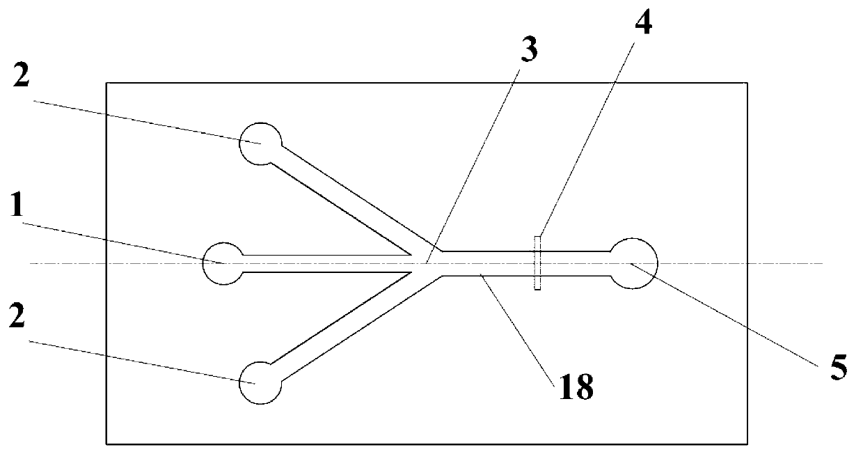
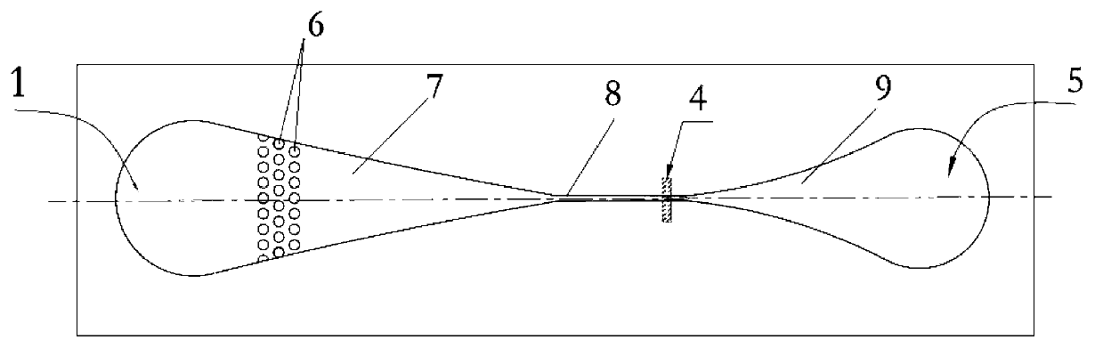
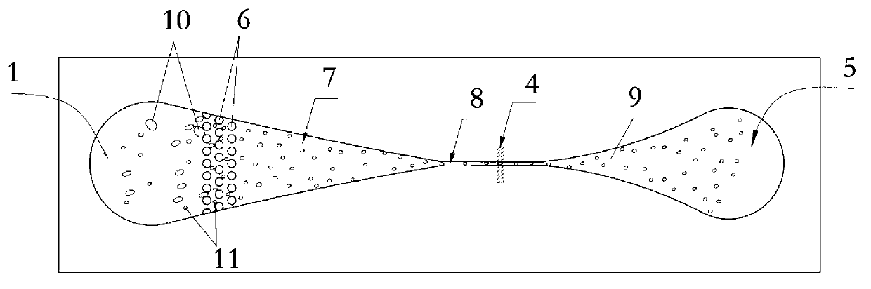
[0029]In this embodiment, a microfluidic chip structure for flow cytometer is used for cell counting of human blood samples, and the maximum cell diameter d0=25 μm in the injected sample liquid mainly includes sample liquid inlet 1, shape Array structure 6, conical focusing structure 7, microchannel 8, detection area 4, flow expansion channel 9, waste liquid outlet port 5; the sample liquid inlet 1 matches the size of the inlet port of the syringe pump; the columnar array structure 6 is located in the conical The focusing structure 7 is close to the inlet 1 of the sample liquid, and the size interval between two adjacent rows of microcolumns is d1=35 μm, so that the columnar array structure 6 has the function of filtering the agglomerated protein impurities and other large biosolid impurities inside the sample liquid , to ensure that the entire chip can work normally; the conical focusing structure 7 has a focusing effect similar to that o...


PUM


Abstract

The invention discloses a micro-fluidic chip structure for a flow cytometer, and a preparation method a micro-fluidic chip. The chip comprises a sample liquid inlet 1, a column array structure 6, a conical focusing structure 7, a micro-channel 8, a detection zone 4, a flow expanding channel 9 and a waste liquid outlet end 5, wherein the column array structure 6 can play a role of filtering agglomerate protein impurities and other large biological solids inside sample liquid; and the conical focusing structure 7 has a focusing effect which is similar to that of the traditional sheath liquid system, so that cell granules flow inside the micro-channel 8 one by one; and the micro-channel 8 restricts the cells through the channel, so that the cells pass through the detection zone 4 one by one. By adopting the chip structure disclosed by the invention, the focusing effect without sheath flow liquid can be achieved; and blockage is not generated, so as to reduce use of the sheath flow liquid; and meanwhile, the situation that the cell granules pass through the detection zone one by one is ensured. The processing method of the micro-fluidic chip is convenient; the used bonding method is a common bonding method, and is simple and convenient to operate; and the used material PDMS (polydimethylsiloxane) is easy to process and has good biocompatibility.

Description

technical field [0001] The invention relates to a structure and a preparation method of a microfluidic chip used for a flow cytometer. Background technique [0002] Flow cytometry is a technology that automatically analyzes and detects cell particles in a liquid flow one by one. Flow cytometer (FCM) is based on the basic principles of flow cytometry, and comprehensively utilizes computer technology, laser technology, mechanical mechanics, cytochemistry, cellular immunology and other technologies to realize cell detection and analysis functions. instrument. Among them, the sample focusing is the key module of the flow cytometer, and the whole focusing process is to realize the focusing effect on the sample liquid through the action of external force. However, the entire system is bulky, complex, and expensive, and the emergence of microfluidic chip technology is expected to miniaturize the focus of cells, thereby miniaturizing the overall system. [0003] At present, the m...

Claims


Application Information

Patent Timeline
IPC IPC(8): B01L3/00G01N15/14
Inventor 常洪龙洪水金寻文鹏冯建国
Owner NORTHWESTERN POLYTECHNICAL UNIV
Why Eureka
Try Eureka