A multi-stage fluidized bed device and method for producing aromatics by catalytic conversion of alcohol/ether

A catalytic conversion, fluidized bed technology, applied in chemical instruments and methods, hydrocarbon production from oxygen-containing organic compounds, chemical recovery, etc., can solve the problem of not ensuring rapid deactivation of catalysts, prolonging catalyst residence time, and increasing wastewater treatment costs, etc. problems, to achieve the effect of rich heat exchange area, low waste water treatment cost, and reduced production cost

Active Publication Date: 2015-10-28
TSINGHUA UNIV +1
View PDF8 Cites 0 Cited by
  • Summary
  • Abstract
  • Description
  • Claims
  • Application Information

AI Technical Summary

Problems solved by technology

The structural parts in the reactor cannot guarantee the operation of prolonging the residence time of the catalyst in the reactor after the catalyst is rapidly deactivated and the gas velocity is increased in this process
In particular, when the catalyst activity is not very low, the alcohol ether conversion is incomplete, and the concentration in the wastewater increases, resulting in a significant increase in the cost of wastewater treatment
This technology solves this problem by increasing the regeneration frequency of the catalyst, but it increases the wear of the catalyst

Method used


Image

  • A multi-stage fluidized bed device and method for producing aromatics by catalytic conversion of alcohol/ether
  • A multi-stage fluidized bed device and method for producing aromatics by catalytic conversion of alcohol/ether
  • A multi-stage fluidized bed device and method for producing aromatics by catalytic conversion of alcohol/ether

Examples


Embodiment 1

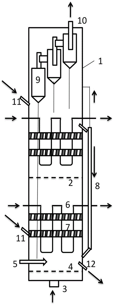
[0083] use figure 1 In the two-stage fluidized bed 1 shown, the distance between the gas distributor 4 and the liquid phase nozzle 5 is controlled to be 0.1 times the diameter of the two-stage fluidized bed 1 . A liquid phase nozzle 5 is extended into the two-stage fluidized bed 1 and fixed on the cylinder wall of the two-stage fluidized bed 1 . The distance between the outlet at the upper end of the outer overflow pipe 8 and the horizontal porous distribution plate 2 below is 0.1 times the diameter of the two-stage fluidized bed 1 . The position of the inlet at the lower end of the outer overflow pipe 8 is in the first catalyst filling section. The two catalyst inlets 11 lead into the two catalyst filling sections respectively, and the position of the uppermost catalyst inlet 11 is 1m higher than the upper outlet of the adjacent outer overflow pipe 8 . The gas contained in the catalyst entering from the outlet at the upper end of the outer overflow pipe 8 is led to the vici...

Embodiment 2

[0088] use figure 1 The two-stage fluidized bed 1 is shown. Control the distance between the gas distributor 4 and the liquid phase nozzle 5 to be 0.05 times the diameter of the fluidized bed. Four liquid phase nozzles 5 are fixed on the cylinder wall of the two-stage fluidized bed 1 and distributed symmetrically, and extend into the two-stage fluidized bed 1 . The distance between the outlet at the upper end of the outer overflow pipe 8 and the horizontal porous distribution plate 2 below is twice the diameter of the two-stage fluidized bed 1 . The position of the inlet at the lower end of the outer overflow pipe 8 is in the first catalyst filling section. The two catalyst inlets 11 lead into the two catalyst filling sections respectively, and the position of the uppermost catalyst inlet 11 is 2m higher than the upper outlet of the adjacent outer overflow pipe 8 . The gas contained in the catalyst entering from the upper outlet of the outer overflow pipe 8 is led to the vi...

Embodiment 3

[0093] use figure 1 The two-stage fluidized bed 1 is shown. Control the distance between the gas distributor 4 and the liquid phase nozzle 5 to be 0.2 times the diameter of the two-stage fluidized bed 1 . Twelve liquid phase nozzles 5 are fixed on the cylinder wall of the two-stage fluidized bed 1 and evenly distributed, and extend into the two-stage fluidized bed 1 . The distance between the outlet at the upper end of the outer overflow pipe 8 and the horizontal porous distribution plate 2 below is 4 times the diameter of the two-stage fluidized bed 1 . The position of the inlet at the lower end of the outer overflow pipe 8 is in the first catalyst filling section. The two catalyst inlets 11 lead into the two catalyst loading sections respectively, and the position of the uppermost catalyst inlet 11 is 1.5m higher than the upper outlet of the adjacent outer overflow pipe 8 . The gas contained in the catalyst entering from the upper outlet of the outer overflow pipe 8 is le...


PUM

PropertyMeasurementUnit
diameteraaaaaaaaaa
densityaaaaaaaaaa
densityaaaaaaaaaa

Abstract

The invention belongs to the technical field of chemical preparation, and in particular relates to a multi-stage fluidized bed device and method for preparing aromatic hydrocarbon by alcohol / ether catalytic conversion. According to the method, a fluidized bed is divided into a plurality of catalyst filling sections through a transverse porous distribution plate, the operation of the fluidized bed can be stabilized by utilizing an overflow pipe, and a reacting raw material can be completely converted through the plurality of catalyst filling sections; the remained raw material can be contacted with a high-activity catalyst by adjusting the flow-rate of the regenerated catalysts at catalyst feed ports in different positions, so that complete conversion can be performed; a low-temperature liquid phase raw material is sprayed through a liquid phase nozzle and is directly vaporized to absorb heat; a low-temperature medium is introduced into a heat exchanger, so that the effects of controlling temperatures of different catalyst filling sections and controlling the coking amount of the catalyst can be played, and raw material preheating or side product steam can be completed. The multi-stage fluidized bed device has the advantages of high operation safety, high production strength of a reactor, high operation elasticity, continuous process, little investment and low energy consumption, is convenient to control temperature, and is suitable for large-scale operation.

Description

technical field [0001] The invention belongs to the technical field of chemical preparation, and in particular relates to a multi-stage fluidized bed device and method for producing aromatics by catalytic conversion of alcohol / ether. Background technique [0002] Aromatics are one of the most important basic chemicals. In the traditional chemical route, aromatics are mainly obtained from petroleum refining and coal dry distillation. The aromatic hydrocarbons obtained by the petroleum route have high purity and are suitable for the preparation of various high-quality chemicals. The aromatics obtained by the coal (carbonization) route contain thiophene impurities, the quality is relatively low, and the application is limited. With the increasing shortage of petroleum resources, the supply of aromatics is tense, and the price remains high, which greatly increases the production of subsequent chemicals. costs, affecting sales. Raw materials such as methanol and dimethyl ether ...

Claims


Application Information

Patent Timeline
Patent Type & Authority Patents(China)
IPC IPC(8): B01J8/28C07C15/02C07C1/20
CPCY02P20/584
Inventor 魏飞骞伟中王彤汤效平崔宇高长平丁焕德
Owner TSINGHUA UNIV
Why Eureka
Try Eureka