Device for horizontally utilizing biomass fuel to continuously produce combustible gases

A biomass fuel, horizontal technology, used in biofuels, special forms of dry distillation, petroleum industry and other directions, can solve the problems of insufficient combustion, inconvenient promotion, air pollution, etc., and achieve simple structure, small environmental impact, and sufficient combustion. Effect

Inactive Publication Date: 2013-12-04
陈星志
View PDF9 Cites 1 Cited by
  • Summary
  • Abstract
  • Description
  • Claims
  • Application Information

AI Technical Summary

Problems solved by technology

Usually, biomass fuel needs to be processed, adding grease, sulfur fixing agent, and combustion accelerant to granulate to facilitate boiler use, such as the "biomass briquette fuel" disclosed by the publication number CN101899345A, which requires processing of biomass fuel Processing also requires supporting granulation and molding equipment, which is expensive and not easy to promote; the publication number is "Biomass Fuel Boiler" disclosed by CN101846386A, and its structure includes an external shell and an internal combustion chamber. Between the shell and the combustion chamber There is a water storage room in between, and there is a burner at the lower part of the combustion chamber. The combustion chamber is a double-layer sleeve structure. The inner layer is a cylinder with an open top, and there is an ignition device in the middle of the bottom. , the inner cylinder is sealed except for the opening, the bottom surface of the inner cylinder and the middle and upper parts of the side have air inlets, and there is a pellet fuel tank on the side of the shell, and the pellet fuel tank is passed through the auger connected to the burner
This kind of device burns biomass fuel directly, and the dryness and fineness of raw materials are strictly selected. Insufficient combustion will generate a large amount of smoke and dust, causing air pollution.

Method used


Image

  • Device for horizontally utilizing biomass fuel to continuously produce combustible gases

Examples


Embodiment

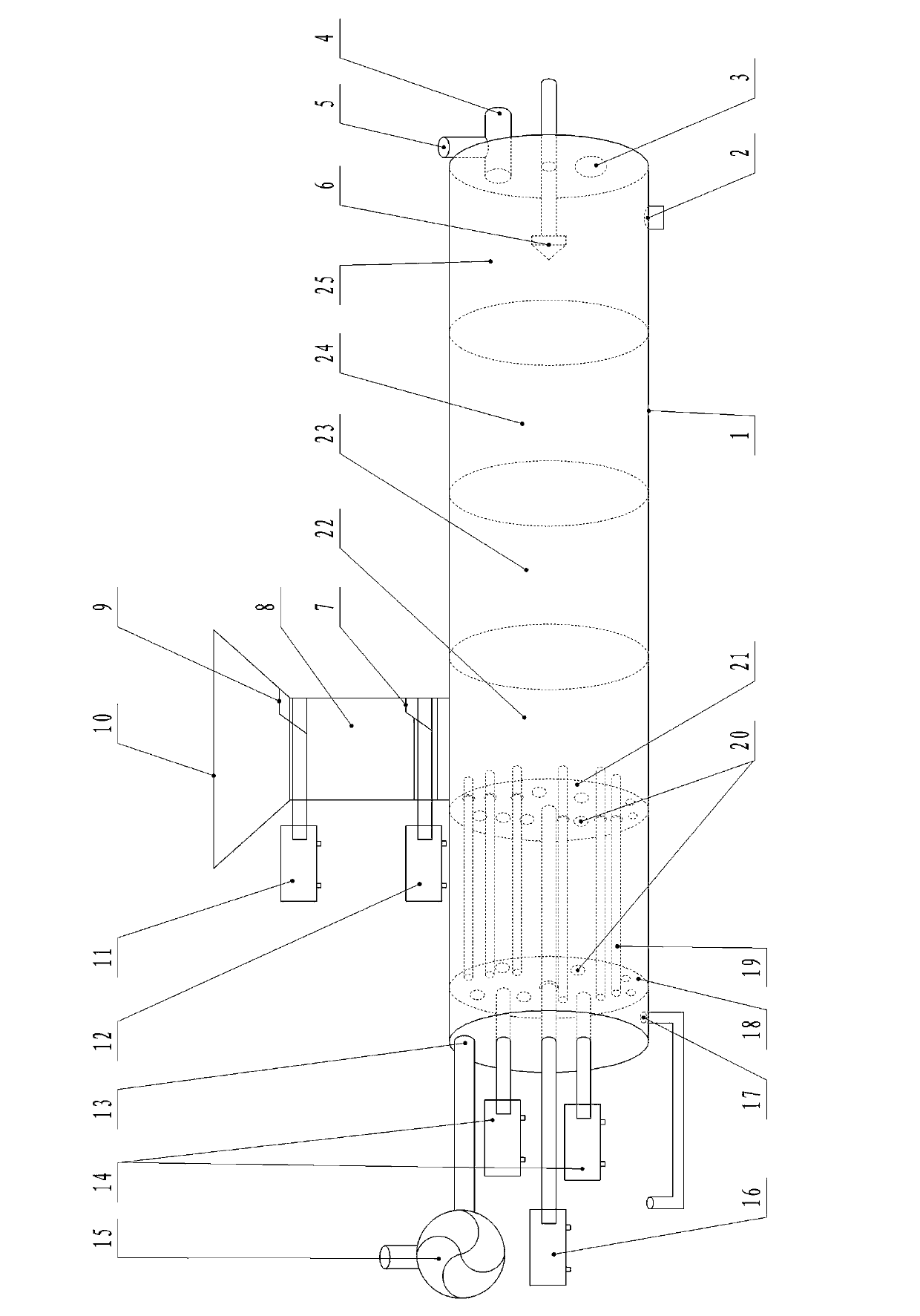
[0015] refer to figure 1 , a horizontal device for continuously producing combustible gas using biomass fuels, comprising a housing 1, the housing 1 is in the shape of a columnar body, placed horizontally, the upper side of the housing 1 is connected to the storage chamber 8, and the storage chamber The upper end of the material chamber 8 is connected with the feed hopper 10; the combustion head 6 is arranged in the inner cavity of the right end of the housing 1, and the air inlet 5 and the waste material outlet 2 are arranged at the right end; The sequence on the right is provided with a punching piston 18 and a pusher piston 21. The punching piston 18 is provided with a plurality of horizontally arranged through rods 19, one end of the through rod 19 is connected with the punching piston 18, and the other end can pass through Pushing piston 21, punching piston 18, and vent hole 20 are arranged on pushing piston 21, and punching piston 18 is connected with second hydraulic cy...


PUM


Abstract

The invention discloses a device for horizontally utilizing biomass fuel to continuously produce combustible gases. The device comprises a housing, and the housing is columnar and horizontally placed. The upper side of the housing is connected with a storage chamber, and the upper end of the storage chamber is connected with a feed hopper. A combustion head is arranged in a right-side inner cavity of the housing, and an air inlet and a waste outlet are formed in the right end part of the housing. A punching piston and a pushing piston are arranged in a left-end inner cavity of the housing from left to right sequentially, and a plurality of horizontal through rods are arranged on the punching piston. One end of each through rod is connected with the punching piston, and the other end of each through rod can penetrate through the pushing piston. Ventholes are formed in the punching piston and the pushing piston, the punching piston is connected with a second hydraulic cylinder, and the pushing piston is connected with a first hydraulic cylinder. A fuel gas outlet communicated with an exhaust fan is formed in the left-end part of the housing. The device has the advantages of simple structure and low cost, can continuously produce the combustible gases in a high-efficient mode, has a lower requirement on raw materials, can sufficiently combust, and has little influence on environment and a higher conversion rate.

Description

technical field [0001] The invention relates to a device for producing combustible gas, in particular to a horizontal device for continuously producing combustible gas by utilizing biomass fuel. Background technique [0002] Biomass fuels include fuels including organic substances such as plant materials and animal wastes, especially those derived from agricultural resources and industrial processing, including various energy plants discarded in agricultural production and processing, such as straw, rice husk, corn cob, peanut Shells, bagasse, cottonseed hulls, wood chips, bamboo chips, etc. These wastes are relatively concentrated, easy to collect and treat, and can be used as biomass fuels. Usually, biomass fuel needs to be processed, adding grease, sulfur fixing agent, and combustion accelerant to granulate to facilitate boiler use, such as the "biomass briquette fuel" disclosed by the publication number CN101899345A, which requires processing of biomass fuel Processing ...

Claims


Application Information

Patent Timeline
Patent Type & Authority Applications(China)
IPC IPC(8): C10B53/02
CPCY02E50/14Y02E50/10
Inventor 陈星志
Owner 陈星志
Why Eureka
Try Eureka