Optical polarization converter and manufacturing method thereof

A manufacturing method and converter technology, applied in the field of electronics, can solve the problems of increasing device insertion loss, complex technical process, complex component components, etc., and achieve the effects of simple structure, simple manufacturing process and high manufacturing precision

Inactive Publication Date: 2013-12-04
XIDIAN UNIV
View PDF3 Cites 10 Cited by
  • Summary
  • Abstract
  • Description
  • Claims
  • Application Information

AI Technical Summary

Problems solved by technology

The disadvantages of this device are: firstly, the changing magnetic field in the polarization controller will cause a large scattering loss to the polarized light passing through the magnetic field; secondly, the integration degree is low
The shortcomings of this device are: first, the device uses germanium doped in silicon to realize the optical waveguide, and the required technical process is complicated; second, doping germanium in silicon will cause light scattering effect, increasing The insertion loss of the device; third, the components of the polarization mode converter of the basic path are complex, which will cause a large insertion loss and low integration;

Method used


Image

  • Optical polarization converter and manufacturing method thereof
  • Optical polarization converter and manufacturing method thereof
  • Optical polarization converter and manufacturing method thereof

Examples


Embodiment Construction

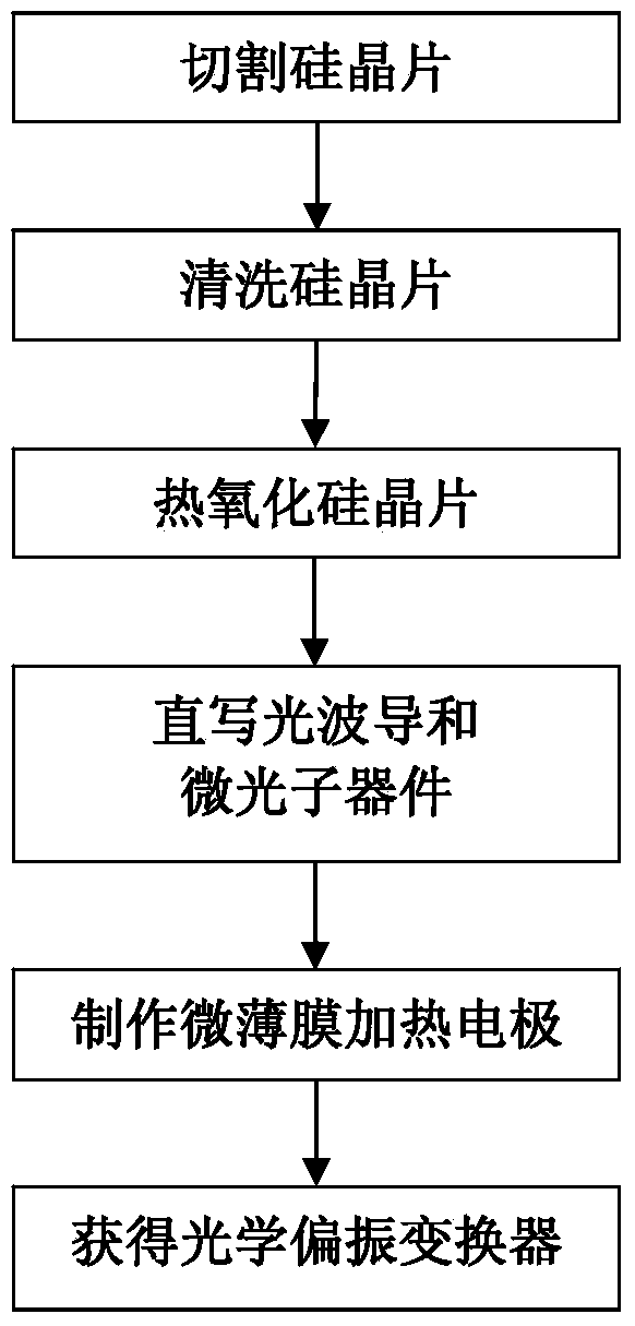
[0034] The present invention will be further described below in conjunction with the accompanying drawings.

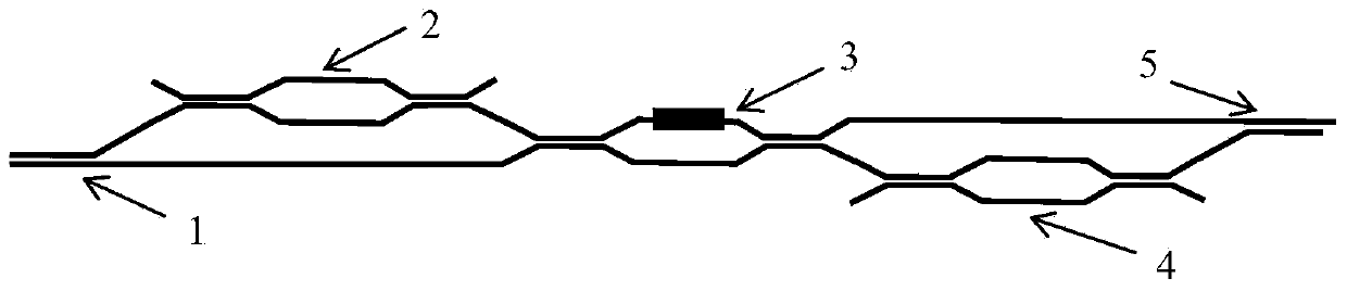
[0035] Refer to attached figure 1 , the optical polarization converter of the present invention includes a three-dimensional 2×2 polarization beam splitter 1, a first half-wave plate 2, an adjustable coupler and a phase shifter made of silicon-based silicon dioxide materials. The combined device 3, the second half-wave plate 4, and the polarization beam combiner 5.

[0036] The polarization beam splitter 1 is located at the leftmost end of the optical polarization converter, and the incident light of any polarization state is decomposed into two beams of linearly polarized light whose polarization directions have an included angle of 90° through the polarization beam splitter 1 .

[0037] The first half-wave plate 2 is connected to the polarization beam splitter 1 through an optical waveguide, and any one of the two beams of linearly polarized light output from the po...


PUM


Abstract

The invention discloses an optical polarization converter and a manufacturing method thereof. The optical polarization converter comprises a polarization beam splitter, a first half-wave plate, a second half-wave plate and a polarization beam combiner. The optical polarization converter is a thermoluminescence type polarization converter, a phase delay unit is introduced by changing the temperature of a silicon dioxide optical waveguide, the light intensity of two beams of polarized light is distributed in any proportion through a combination device of a tunable coupler and a phase shifter, and the polarization state of light is further accurately converted in real time. The manufacturing method of the optical polarization converter comprises the following steps of: (1) cutting a silicon wafer; (2) cleaning the silicon wafer; (3) thermally oxidizing the silicon wafer; (4) directly writing an optical waveguide and a micro photon device; and (5) manufacturing a micro-thin film heating electrode. The optical polarization converter has the advantages of low loss, simplicity and accuracy in manufacturing, high integration degree, small driving voltage and low power consumption, and can be used for accurately converting the polarization state of the light in real time.

Description

technical field [0001] The invention belongs to the field of electronic technology, and further relates to an optical polarization converter and a manufacturing method thereof in the optical element manufacturing technology in the field of microelectronics. The optical polarization converter provided by the invention can be used for real-time and precise transformation of the optical polarization state. The manufacturing method of the present invention is for the integration of polarization converters and other optoelectronic devices, and provides a simple method of using femtosecond pulses to directly write in silicon-based silicon dioxide photonic waveguides and realize the waveguides and micro-optical devices required by polarization converters. , fast, low cost, high production precision method. Background technique [0002] The accumulation of polarization-dependent losses in multiple optical devices and polarization-dependent gains in multi-stage Erbium-doped amplifie...

Claims


Application Information

Patent Timeline
Patent Type & Authority Applications(China)
IPC IPC(8): G02F1/01G02B6/13
Inventor 王军利谢阳朱江峰魏志义
Owner XIDIAN UNIV
Why Eureka
Try Eureka