Dry method selective solid material separation device

A solid material and separation device technology, applied in the direction of solid separation, separating solids from solids with airflow, chemical instruments and methods, etc., can solve problems such as increased energy consumption of equipment, restrictions on the development of electric separation, immature processes, etc. Achieve low cost, good environmental protection effect, and avoid secondary pollution

Inactive Publication Date: 2013-12-11
中能东讯新能源科技(大连)有限公司 +1
View PDF6 Cites 4 Cited by
  • Summary
  • Abstract
  • Description
  • Claims
  • Application Information

AI Technical Summary

Problems solved by technology

[0006] The principle of dry electric separation is to separate the fly ash from the carbon due to the different conductivity of the ash and carbon under the action of a high-voltage electric field. Safety and economic issues as well as collection and dust removal of fine ash restrict the further development of electric separation; electric separation has not been widely used due to low decarbonization efficiency and immature technology
[0007] Wet flotation decarbonization is a method of distinguishing fly ash and coal nuclei by using the difference in hydrophilic properties of the surface. It is suitable for fly ash discharged by wet method, and the recovery rate is high, but its disadvantages are: After flotation, coal ash needs to be concentrated, dehydrated, dried, sorted, and ground to obtain high-quality fly ash. This process is complicated and the energy consumption of equipment increases.

Method used


Image

  • Dry method selective solid material separation device
  • Dry method selective solid material separation device

Examples


Embodiment Construction

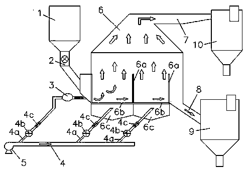
[0016] figure 1 A working system diagram of a dry selective solid material separation device is shown. In the figure, the dry selective solid material separation device includes a solid mixture material storage bin 1, a feeder 2, a fluidized separation bed 6, a blower 5, an air conveying main pipe 4, an air connection box 3, a high-density material storage bin 9 and The low-density material storage bin 10, the solid mixture material storage bin 1 is connected to the fluidized separation bed 6 through the feeder 2, the bottom outlet of the fluidized separation bed 6 is connected to the high-density material storage bin 9 through the conveying pipeline 8, and the top outlet passes through the upper air outlet. The channel 7 is connected to the low-density material storage bin 10 . The air conveying main pipe 4 connected with the blower 5 is provided with an air conveying branch pipe 4a, a flow control valve 4b and a flow meter 4c are installed on the air conveying branch pipe 4...


PUM


Abstract

The invention discloses a dry method selective solid material separation device, and belongs to the technical field of material gravity separation methods. An outlet in the bottom of a fluidization separation bed of the separation device is connected with a high-density material storage bin through a conveying pipeline. An outlet in the top of the fluidization separation bed of the separation device is connected with a low-density material storage bin through an upper portion air channel. An air conveying main pipe connected with an air blower is provided with air conveying branch pipes. One air conveying branch pipe is connected with an outlet pipeline of a feeding device through an air connecting box. The other air conveying branch pipes are respectively connected with an air bellow at the bottom of the fluidization separation bed. According to the dry method selective solid material separation device, a physical method is applied to separation of solid mixed materials, the form of water-soluble substances in the materials can not be damaged, intrinsic physicochemical properties of the materials can be kept, the separated materials can be further utilized, secondary pollution is avoided in the whole separation process, and the dry method selective solid material separation device has the best environmental-friendly effect. Meanwhile, the dry method selective solid material separation device is simple in structure, easy and convenient to operate and manage, free of adding other separation media, low in cost, and applicable to the separation of a majority of materials with different densities.

Description

technical field [0001] The invention relates to a dry method selective solid material separation device, which belongs to the technical field of material gravity separation method separation. Background technique [0002] In the production process of metallurgy, electric power, coal, chemical industry, mineral processing and other industries, it is often necessary to separate solid materials into different products according to certain requirements to meet production needs or increase their use value. At present, according to different separation purposes and the differences in the physical and chemical properties of materials, the separation methods mainly include flotation method, electromagnetic separation method, gravity separation method, etc. These methods have their own applicable conditions. Chemistry is the subject basis, and the separation of different materials is realized according to the differences in the physical and chemical properties of the surfaces of diff...

Claims


Application Information

Patent Timeline
Patent Type & Authority Applications(China)
IPC IPC(8): B07B7/01
Inventor 唐遵义梁家鼎朱颖
Owner 中能东讯新能源科技(大连)有限公司
Why Eureka
Try Eureka