Laser-electric arc composite spot welding method for pulsed wire feeding

A technology of pulsating wire feeding and recombination points, which is applied in welding equipment, metal processing equipment, manufacturing tools, etc., can solve the problems of easy formation of air holes or cavities in keyholes, small diameter of solder joint fusion surface, low energy utilization solder joints, etc. , to achieve the effects of reducing slump defects, improving utilization, and increasing the range of energy action

Active Publication Date: 2013-12-11
HARBIN INST OF TECH
View PDF3 Cites 11 Cited by
  • Summary
  • Abstract
  • Description
  • Claims
  • Application Information

AI Technical Summary

Problems solved by technology

[0005] The purpose of the present invention is to solve the problems of too small diameter of solder joint fusion surface in the existing laser spot welding process, the collapse of solder joints caused by material evaporation, burning loss an

Method used


Image

  • Laser-electric arc composite spot welding method for pulsed wire feeding
  • Laser-electric arc composite spot welding method for pulsed wire feeding
  • Laser-electric arc composite spot welding method for pulsed wire feeding

Examples


specific Embodiment approach 1

[0023] Specific embodiment one: a kind of pulsating wire-feeding laser-arc compound spot welding method of this embodiment is carried out as follows:

[0024] Step 1: Before welding, grind or clean the surface of the workpiece to be welded, and fix the polished or cleaned workpiece to be welded on the welding fixture;

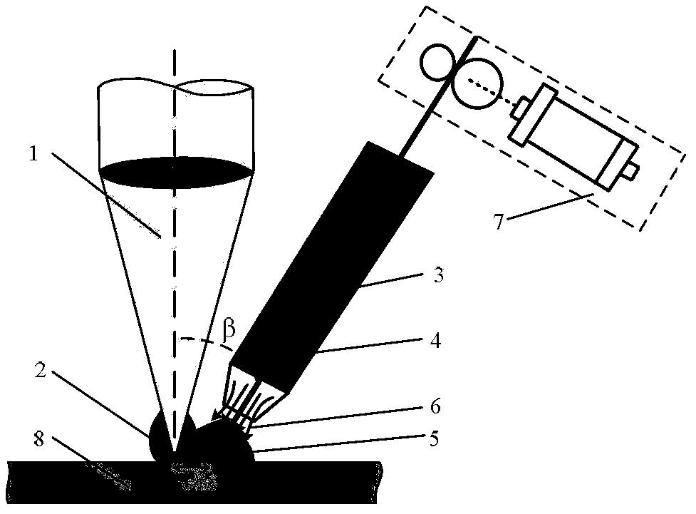
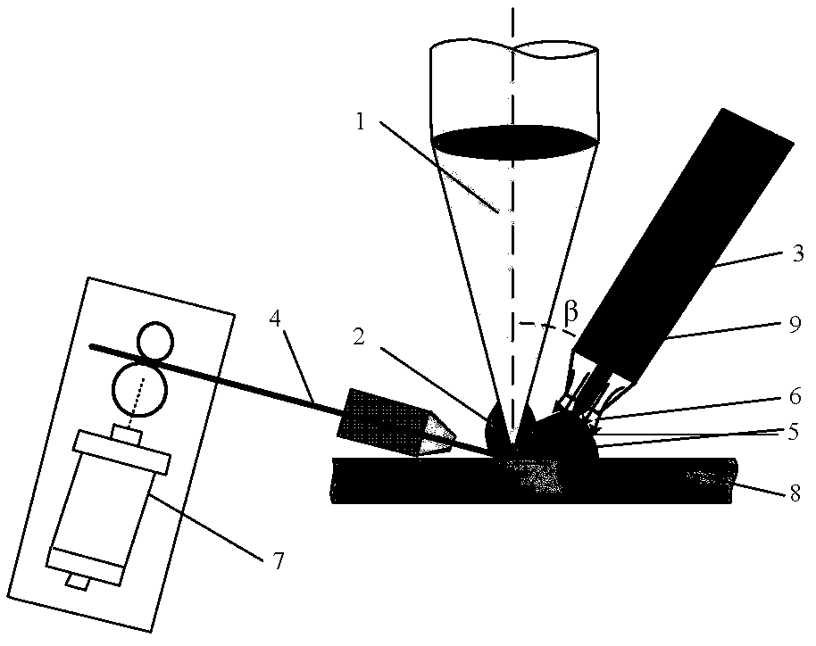
[0025] Step 2: Adjust the position and angle of the laser welding head of the laser and the arc welding torch of the arc welding, so that the laser beam is vertically incident on the surface of the workpiece. The included angle between directions is 30°~45°;

[0026] Step 3: Set the laser-arc composite spot welding process parameters, the laser power P is 0.5kW-10kW, the arc current I is 30A-400A, and the spot welding time t is 0.5s-10s;

[0027] Step 4: Set the wire feeding parameters of the wire feeding machine, the wire feeding speed v is 0.1m / min~2m / min, and the wire drawing speed is 0.1m / min~1m / min;

[0028] Step 5: Start the control switch to carry out ...

specific Embodiment approach 2

[0033] Specific embodiment 2: The difference between this embodiment and specific embodiment 1 is that the difference between this embodiment and specific embodiments 1 to 8 is that the laser described in step 2 is CO 2 laser, YAG laser, fiber laser or semiconductor laser. Others are the same as in the first embodiment.

specific Embodiment approach 3

[0034] Specific implementation mode three: combination figure 1 The difference between this embodiment and specific embodiments 1 to 3 is that the arc welding described in step 2 is gas metal arc welding (GMA welding) or tungsten inert gas arc welding (TIG welding). Others are the same as in the first or second embodiment.


PUM


Abstract

The invention provides a laser-electric arc composite spot welding method for pulsed wire feeding, and relates to a laser spot welding method. The method mainly solves the problems of small diameter of fusion surface of welding points, collapsing of the welding points, easy formation of air pores and cavities, low energy utilization rate and poor adaptability of the welding points to the clearance in the existing laser spot welding process. The method comprises the following steps of 1, pretreating a welding workpiece; 2, adjusting the position and the angle of mutual action of a laser welding head of a laser device and an electric arc welding gun; 3, setting parameters of the laser-electric arc composite spot welding process; 4, setting the wire feeding parameters of a wire feeding machine; and 5, starting a control switch to perform the laser-electric arc composite spot welding for the pulsed wire feeding. The method has the advantages that the diameter of the fusion surface of the welding points is increased, the collapsing of the welding points is reduced, the cracking trend and the formation of the air pores are reduced, the energy utilization rate is improved, and the appearance of the welding points is attractive; the method is mainly used for welding metal material, and is especially suitable for welding metal material overlap joints.

Description

technical field [0001] The invention relates to a laser spot welding welding method. Background technique [0002] With the rapid development of laser technology in recent years, it has become more and more widely used in the fields of automobile manufacturing and aerospace weaponry. It has played a role in replacing resistance spot welding and riveting in actual production, especially in the automobile industry. It not only improves the production efficiency, but also can reduce the structural weight and quickly adapt to the upgrading of products. Compared with the traditional spot welding method, laser spot welding has the advantages of small heat input, narrow welding heat-affected zone, fast welding speed, good flexibility, and deformation. It has the characteristics of small size, low application requirements, easy realization and harmless to human body. [0003] At the same time, laser spot welding also has some shortcomings: due to the small diameter of the single la...

Claims


Application Information

Patent Timeline
IPC IPC(8): B23K28/02
Inventor 陈彦宾雷正龙吕涛乔亮胡佩佩金诚
Owner HARBIN INST OF TECH
Why Eureka
Try Eureka