Single-driven ultrasonic elliptical vibration turning device

A technology of elliptical vibration and ultrasonic vibration, which is applied in turning equipment, auxiliary devices, fluids using vibration, etc., can solve the problems that restrict the application and promotion of ultrasonic elliptical vibration transducers, the complex structure of ultrasonic vibration system and control system, and the influence of ultrasonic elliptical vibration. Vibration cutting effect and other problems, to achieve the effect of simplifying the control circuit and ultrasonic power supply structure, simple structure and low cost

Active Publication Date: 2013-12-18
SUZHOU UNIV OF SCI & TECH
View PDF7 Cites 27 Cited by
  • Summary
  • Abstract
  • Description
  • Claims
  • Application Information

AI Technical Summary

Problems solved by technology

At present, most researchers use two vibration forms of longitudinal vibration, torsional vibration, bending vibration and radial vibration to combine to generate ultrasonic elliptical vibration. If there are two or more vibration modes, each group of piezoelectric ceramic sheets must be equipped with an ultrasonic drive power signal, and the phase difference between the ultrasonic drive power signals needs to be controlled. The structure of the ultrasonic vibration system and control system is complex. , high manufacturing difficulty, high control difficulty, high production cost, difficult miniaturization, and unstable working performance, these problems restrict the application and promotion of ultrasonic elliptical vibration transducers in industrial production
[0003] In order to overcome the deficiencies in the above-mentioned ultrasonic elliptical vibration transducer technology, the paper "Elliptic Vibration Cutting Transducer Based on Finite Element Analysis" of "Journ

Method used


Image

  • Single-driven ultrasonic elliptical vibration turning device
  • Single-driven ultrasonic elliptical vibration turning device

Examples


Embodiment Construction

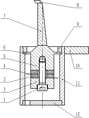
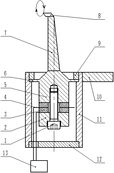
[0017] combine figure 1 , 2 As shown, the single excitation ultrasonic elliptical vibration turning device includes a housing unit, an ultrasonic vibration transducer placed in the housing unit, an elliptical vibration mode converter 7 and a tool 8 arranged at the front end of the elliptical vibration mode converter 7; The housing unit includes an upper cover plate 9, a support plate 10, an outer sleeve 11 and a lower cover plate 12. One end of the support plate 10 is welded on the outer circle of the outer sleeve 11, and the other end is fixed on the lathe tool holder to connect with the machine tool; ultrasonic vibration The outer contour of the transducer is cylindrical, which includes a bolt 1 and a rear cover 2, a piezoelectric ceramic sheet 3, an electrode sheet 4 and a front cover 5 which are sequentially sleeved on the bolt 1. The front cover 5 is provided with a The flange 6 used for the connection of the housing unit, the rear cover 2 and the front cover 5 connect a...


PUM


Abstract

The invention discloses a single-driven ultrasonic elliptical vibration turning device, comprising a shell unit, an ultrasonic vibration transducer, an elliptical vibration mode converter and a cutter, wherein the ultrasonic vibration transducer is arranged in the shell unit; the cutter is arranged on the front end of the elliptical vibration mode converter; the shell unit comprises an upper cover plate, a support plate, an external sleeve and a lower cover plate; the ultrasonic vibration transducer comprises a bolt, a rear cover plate, piezoelectric ceramic pieces, an electrode slice and a front cover plate; the rear cover plate, the piezoelectric ceramic pieces, the electrode slice and the front cover plate are sheathed on the bolt in sequence; the rear cover plate and the front cover plate enable the rear cover plate, the piezoelectric ceramic pieces, the electrode slice and the front cover plate to be linked and pressed through the bolt; the elliptical vibration mode converter is arranged on the front end of the front cover plate and is of an oblique wedge-shaped structure; the elliptical vibration mode converter can enable longitudinal ultrasonic vibration generated by the ultrasonic vibration transducer to be converted to the longitudinal-flexural composite ultrasonic elliptical vibration of the end of the elliptical vibration mode converter and the cutter.

Description

technical field [0001] The invention relates to the field of ultrasonic vibration utilizing the inverse piezoelectric effect of piezoelectric ceramics, in particular to a single excitation ultrasonic elliptical vibration turning device. Background technique [0002] Ultrasonic elliptical vibration is widely used in the fields of ultrasonic vibration cutting, ultrasonic welding, ultrasonic grinding, ultrasonic polishing, linear ultrasonic motor and rotary ultrasonic motor. At present, most researchers use two vibration forms of longitudinal vibration, torsional vibration, bending vibration and radial vibration to combine to generate ultrasonic elliptical vibration. If there are two or more vibration modes, each group of piezoelectric ceramic sheets must be equipped with an ultrasonic drive power signal, and the phase difference between the ultrasonic drive power signals needs to be controlled. The structure of the ultrasonic vibration system and control system is complex. , ...

Claims


Application Information

Patent Timeline
IPC IPC(8): B23B25/00B06B1/06
Inventor 殷振李华曹自洋李艳刘义生吴永芝陈玉荣任坤吕自强刘娇
Owner SUZHOU UNIV OF SCI & TECH
Why Eureka
Try Eureka