Plasma CVD apparatus, plasma CVD method, reactive sputtering apparatus, and reactive sputtering method

A plasma and gas technology, applied in the field of plasma CVD equipment, can solve the problems of unrecorded particle countermeasures and abnormal discharge, etc., and achieve the effects of inhibiting the adhesion and fouling of the electrode surface, inhibiting the film forming speed, and ensuring the film forming speed

Active Publication Date: 2013-12-18
TORAY IND INC
View PDF10 Cites 8 Cited by
  • Summary
  • Abstract
  • Description
  • Claims
  • Application Information

AI Technical Summary

Problems solved by technology

[0008] In addition, in Patent Document 2, in order to suppress the generation of particles in the gas phase, it is preferable to make the pressure in the vacuum vessel 1 Pa or less, but there is no description about the particle countermeasures as the device structure.
Furthermore, the silane compound as a raw material is supplied from the raw material introduction duct (raw material ejection part), but if a protrusion such as the duct is arranged near the plasma region in this way, especially when high-frequency power is used, it may become Cause of Abnormal Discharge

Method used


Image

  • Plasma CVD apparatus, plasma CVD method, reactive sputtering apparatus, and reactive sputtering method
  • Plasma CVD apparatus, plasma CVD method, reactive sputtering apparatus, and reactive sputtering method
  • Plasma CVD apparatus, plasma CVD method, reactive sputtering apparatus, and reactive sputtering method

Examples


Embodiment 1

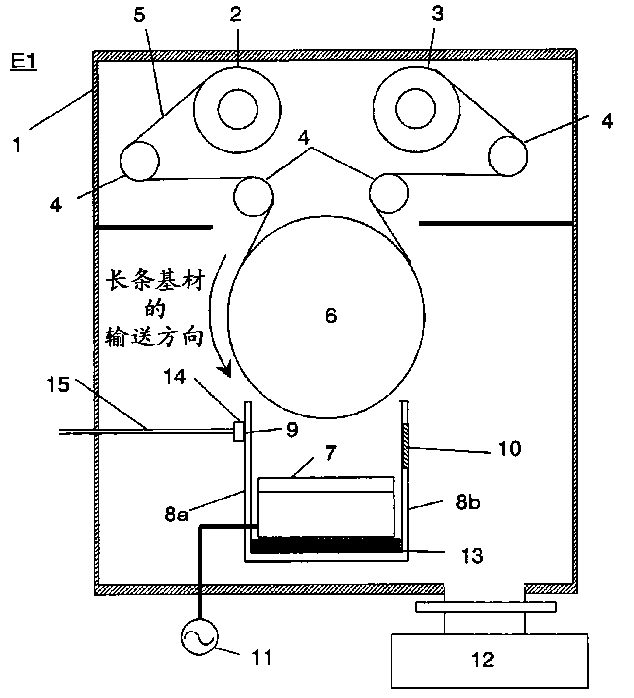
[0156] use figure 1 In the plasma CVD apparatus E1 shown, the state of the plasma during the formation of the silicon oxide film and the state of the electrodes after the film formation were observed based on the first embodiment of the silicon oxide film forming method described above.

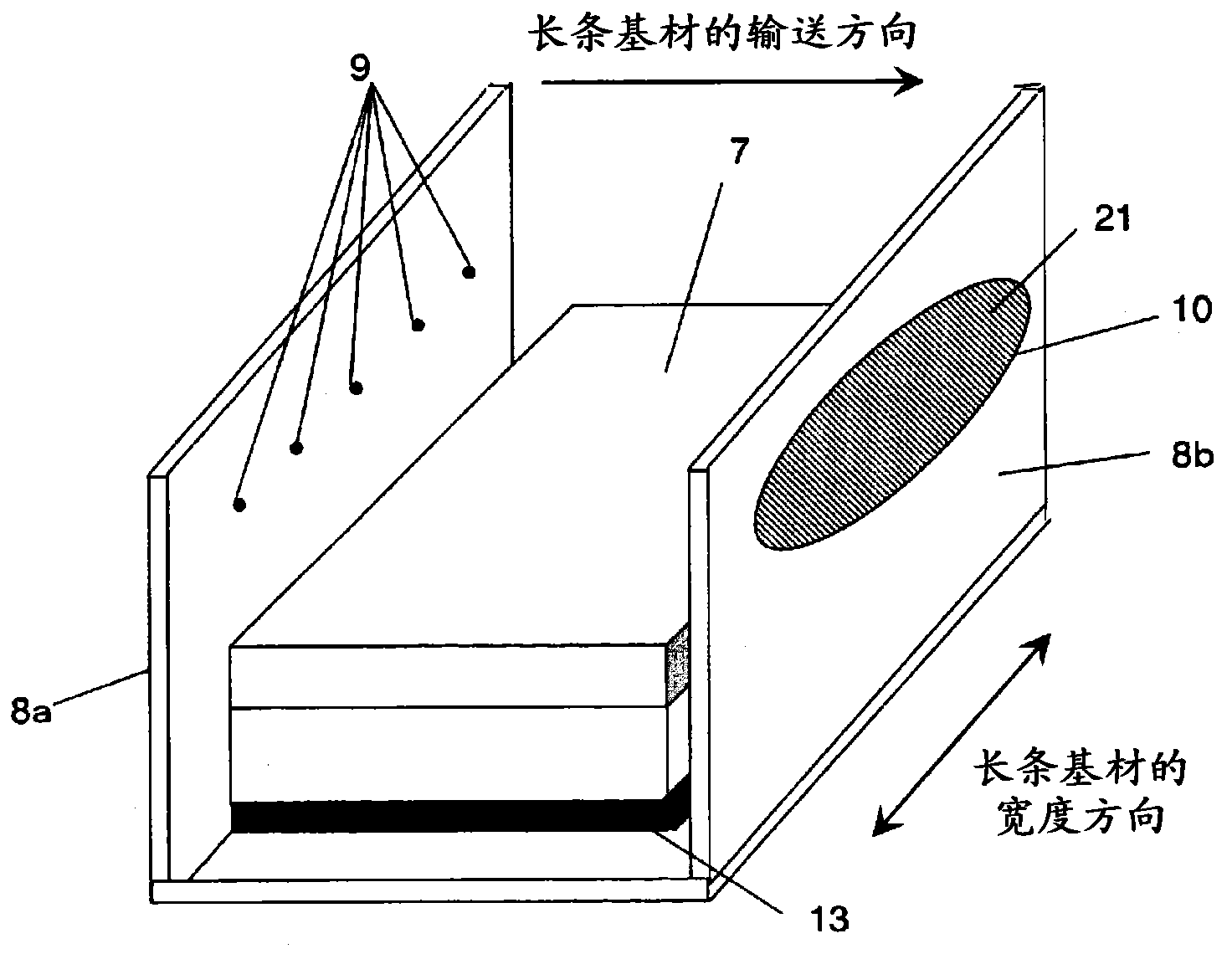
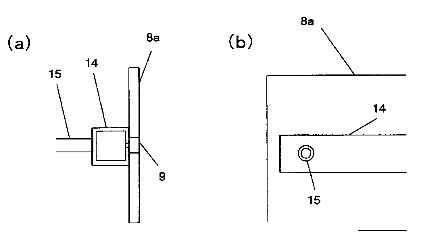
[0157] In the plasma CVD apparatus E1, the main roll 6 has a diameter of 500 mm and a width of 340 mm. The plasma generating electrode 7 was formed by combining a titanium plate with a length of 236 mm, a width of 80 mm, and a thickness of 6 mm, and a SUS box with a length of 236 mm, a width of 80 mm, and a height of 30 mm. Cooling water flows through the SUS tank to cool the titanium plate. The thickness of the side walls 8a, 8b is 3mm. The height of the side walls 8a and 8b was 50 mm from the main roll side surface of the plasma generating electrode 7, and the length in the width direction was 248 mm. On the side wall on the upstream side with respect to the conveying direction ( figu...

Embodiment 2

[0163] use Figure 4 In the plasma CVD apparatus E2 shown, the state of the plasma during the formation of the silicon oxide film and the state of the electrodes after the film formation were observed based on the second embodiment of the silicon oxide film forming method described above. The gas supply hole row 9 for supplying the source gas is arranged at the same position as in the first embodiment. In addition, at a position 9 mm away from the gas supply hole row 9 for supplying the raw material gas to the plasma discharge electrode 7 side, another row of gas supply hole row 9 is formed, and a carrier gas different from the carrier gas is introduced from this gas supply hole row. Ar. As a raw material gas, 0.1 g / min of HMDSO was vaporized with 50 sccm of Ar as a carrier gas by a gasification supplier (not shown), and mixed with 100 sccm of oxygen. In addition, unlike the source gas, 50 sccm of Ar was supplied from the gas supply hole array in the lower stage. Other part...

Embodiment 3

[0166] use Figure 5 In the plasma CVD apparatus E3 shown, the state of the plasma during the formation of the silicon oxide film and the state of the electrodes after the film formation were observed based on the third embodiment of the silicon oxide film forming method described above. A neodymium magnet 16 with a width of 10 mm and a height of 15 mm was arranged inside the SUS case of the plasma generating electrode 7 , and cooling water was made to flow in the cooling water flow path 17 . Other parts are the same as in Example 2.

[0167] The film formation speed was 45nm·m / min without a magnet, but increased to 110nm·m / min with a magnet. In addition, as shown in Table 2, stable formation was possible without abnormal discharge. membrane. In addition, electrode fouling after film formation is also reduced.


PUM

PropertyMeasurementUnit
widthaaaaaaaaaa
thicknessaaaaaaaaaa
heightaaaaaaaaaa

Abstract

Provided is a plasma CVD apparatus that is a vacuum film formation apparatus provided with a main roll and a plasma generating electrode in a vacuum container, and forming a thin film on a surface of an elongated base material while transporting the elongated base material along a surface of the main roll, wherein at least one side wall extending in the width direction of the elongated base material is provided on each of an upstream side and a downstream side in the transportation direction of the elongated base material and sandwiches a film forming space so as to surround the film forming space sandwiched between the main roll and the plasma generating electrode, the side walls are electrically insulated from the plasma generating electrode, and at least one row of a gas supply hole row that forms a plurality of gas supply holes aligning in the width direction of the elongated base material is provided on either one of the side walls on the upstream side and the downstream side of the transportation direction of the elongated base material.

Description

technical field [0001] The present invention relates to a plasma CVD apparatus and a plasma CVD apparatus for generating plasma in the gap between a long substrate and a plasma generating electrode, and using the formed plasma to chemically react supplied source gases to form a thin film on the surface of a long substrate. Method and reactive sputtering device, reactive sputtering method. Background technique [0002] So far, many researches have been carried out to apply DC power or high-frequency power to the plasma generating electrode in a vacuum container capable of transporting long substrates such as polymer film substrates to form plasma, and use this plasma to chemically convert the raw material gas. Reaction, plasma CVD equipment and plasma CVD method to form desired thin film. On the other hand, the reactive sputtering method is a technique of reacting target atoms ejected by sputtering with gases such as oxygen and nitrogen, and depositing the resulting substanc...

Claims


Application Information

Patent Timeline
Patent Type & Authority Applications(China)
IPC IPC(8): C23C16/455C23C14/34
CPCC23C14/562C23C16/50C23C16/401C23C16/402C23C16/545H01J37/32559H01J37/32568H01J37/32752H01J37/3277H01J37/3405H01J37/3417H01J2237/3321H01J2237/3325C23C14/0068C23C16/45517C23C14/0063C23C16/455C23C14/34
Inventor 江尻广惠坂本桂太郎野村文保植田征典
Owner TORAY IND INC
Why Eureka
Try Eureka