High-purity chlorine gas rectifying technology and equipment thereof

A high-purity chlorine gas and process technology, applied in the direction of chlorine/hydrogen chloride, chlorine/hydrogen chloride purification, etc., can solve the problems of strict water content of raw material chlorine, failure to meet high output, corrosion of equipment and pipelines, etc. The effect of less and saving investment

Active Publication Date: 2013-12-25
北京华宇同方化工科技开发有限公司
View PDF2 Cites 10 Cited by
  • Summary
  • Abstract
  • Description
  • Claims
  • Application Information

AI Technical Summary

Problems solved by technology

The high-purity chlorine gas produced by the adsorption method needs to prepare desiccant and adsorbent that are not corroded by chlorine gas and do not chemically react with chlorine, and the selection of appropriate drying, adsorption, regeneration and condensation process conditions is a subject with great technical difficulty and a lot of research content. , the adsorption method equipment is simple, has certain limitations, and cannot meet the requirements of high output
[0004] The separation process of high-purity chlorine produced by condensation method is simple and can remove O 2 , N 2 , CO 2 , CO, H 2 、CH 4 Such as low boiling point impurities, but it is difficult to remove trace water in chlorine gas, and the water content in raw material chlorine is very strict, otherwise it will block, corrode equipment and pipelines, etc.

Method used


Image

  • High-purity chlorine gas rectifying technology and equipment thereof
  • High-purity chlorine gas rectifying technology and equipment thereof

Examples


Embodiment Construction

[0042] The preferred embodiments of the present invention will be described below, and it should be understood that the preferred embodiments described herein are only used to illustrate and explain the present invention, but not to limit the present invention. Unless otherwise specified, the percentages used in the present invention are volume percentages.

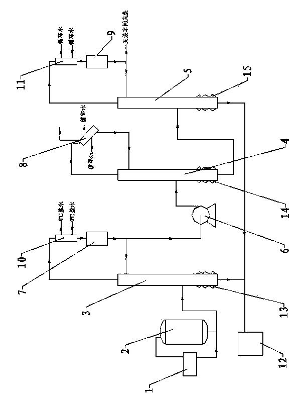
[0043] example, as figure 1 As shown, a kind of high-purity chlorine rectification process, comprises the following steps:

[0044] 1) Open the liquid phase valve of the raw material tank, namely chlorine cylinder 1, and pour liquid chlorine into vaporizer 2. When the weight of the raw material tank, namely chlorine cylinder 1, does not change within 30 minutes, the liquid in chlorine cylinder 1 and vaporizer 2 will not change. bit balance.

[0045] After balancing, open the hot water regulating valve, and slowly increase the pressure of the system through the vaporizer 2 until the liquid chlorine pressure reaches 1.2MP...


PUM


Abstract

The invention relates to a high-purity chlorine gas rectifying technology. The technology comprises the following steps: delivering industrial liquid chlorine to a vaporizer, and sending vaporized chlorine into a first distillation tower under the pressure of 1.2 Mpa until the liquid level of the first distillation tower reach 85%; boosting the pressure of the first distillation tower to 1.0 Mpa, condensing the vaporized chlorine by a first condenser, then sending into a first reflux tank, and delivering 60% residue in the first reflux tank to a second distillation tower; enabling the liquid level of the first reflux tank to be 30% to 40%, and boosting the pressure of the second distillation tower to be 1.8 Mpa; back flowing residue condensed by a second condenser in to the second distillation tower, then sending into a third distillation tower, controlling the liquid level of the second distillation tower to be 60% to 75% until the liquid level of the third distillation tower reaches 85%, and boosting the pressure of the third distillation tower to be 1.5 Mpa; condensing by a third condenser, then sending into a third reflux tank until the purity reaches 99.9999%, enabling the liquid level of the third reflux tank to reach 60%, enabling the purity of the liquid chlorine in the third reflux tank to be 99.9999%, and obtaining high-purity chlorine gas. Through the adoption of the method, raw material input and product output can be carried out stably and continually, the production capacity can be improved, energy consumption can be reduced through continuous rectification, the running is stable, and the operation is safe.

Description

technical field [0001] The invention relates to a rectification process, in particular to a high-purity chlorine gas rectification process and equipment thereof, belonging to the technical field of high-purity chlorine gas production. Background technique [0002] Chlorine gas is one of the main products of the chlor-alkali industry and is a strong oxidant and chlorinating agent. High-purity chlorine gas is a high-purity gas obtained by purifying industrial liquid chlorine. It is used as standard gas and calibration gas. In addition, its applications include microelectronics, optical fiber cables, high-temperature superconductivity, high-performance alloy smelting, and related industries and basic sciences. Research and other cutting-edge technology fields. [0003] For a long time, my country's high-purity chlorine has been dependent on imports. In the 1980s and 1990s, my country only had high-purity chlorine produced by adsorption purification method, and its purity could...

Claims


Application Information

Patent Timeline
Patent Type & Authority Applications(China)
IPC IPC(8): C01B7/07
Inventor 杨秀玲苗乃芬李建学
Owner 北京华宇同方化工科技开发有限公司
Why Eureka
Try Eureka