Crosslinked polyethylene cable residual life assessment method

A cross-linked polyethylene and evaluation method technology, which is applied in the field of evaluation of the remaining life of cross-linked polyethylene cables, can solve the problems of ambiguity in dielectric strength and loss factor, and quantitatively determine the remaining life of cables, achieving high reliability and credibility , The evaluation method is simple, economical and practical

Active Publication Date: 2013-12-25
BAOSHAN IRON & STEEL CO LTD +1
View PDF6 Cites 26 Cited by
  • Summary
  • Abstract
  • Description
  • Claims
  • Application Information

AI Technical Summary

Problems solved by technology

The relationship between the specific dielectric strength and the loss factor is ambiguous. The dielectric strength depends on the weakest link in the cable (where the electrical tree is the largest), and the loss factor depends on the average condition of the cable (average electrical tree growth). Loss tangent value to quantitatively judge the remaining life of the cable

Method used


Image

  • Crosslinked polyethylene cable residual life assessment method
  • Crosslinked polyethylene cable residual life assessment method
  • Crosslinked polyethylene cable residual life assessment method

Examples


Embodiment 1

[0090] The raw material yard is responsible for the transportation of raw materials for the main production line. There are 266 3kV high-voltage loop cables in the whole area, and the cumulative cable length exceeds 125 kilometers. The cables in the raw material field have been put into operation for 22 years until 2004. In order to understand the insulation performance and life of the cables in this area, the cables (same circuit) in two environments were taken out in 2004. The two environments are directly buried respectively. and racks. The cable was manufactured by Tengcang Cable Company in Japan in 1980. The sample cable consists of three loops, the operating voltage of the cable is 3kV, the designed dielectric strength of the main insulation is 20kV / mm, the main material of the cable insulation is XLPE, the thickness of the main insulation is 2.5mm, and the section is 3×35mm2. The power supply system of the raw material field is a small resistance grounding system.

[...

Embodiment 2

[0106] The operating voltage of the sample cable is 3kV or 10kV, the design withstand strength of the main insulation is 20kV~30kV / mm, the main material of the cable insulation is XLPE, the thickness of the 3kV main insulation is 4mm, and the cross-section is 3×250mm2, and the thickness of the 10kV main insulation is 5mm, the section is 3×240mm2. The energy ring power supply system is a small resistance grounding system.

[0107]Table 5 is the step-by-step breakdown voltage data of 3kV cables, Table 6 is the step-by-step breakdown voltage data of 10kV cables made in Japan for direct burial laying, and Table 7 is the step-by-step breakdown voltage data of domestic 10kV cables for direct burial laying. Among them, direct buried cables have been affected by groundwater for a long time.

[0108]

[0109] table 5

[0110] It can be obtained from Table 5 that the residual breakdown voltage of the cable is at least greater than 46.2kV, then:

[0111] Sd=[H*E-Sy] / N=(4×20-46.8)÷2...


PUM


Abstract

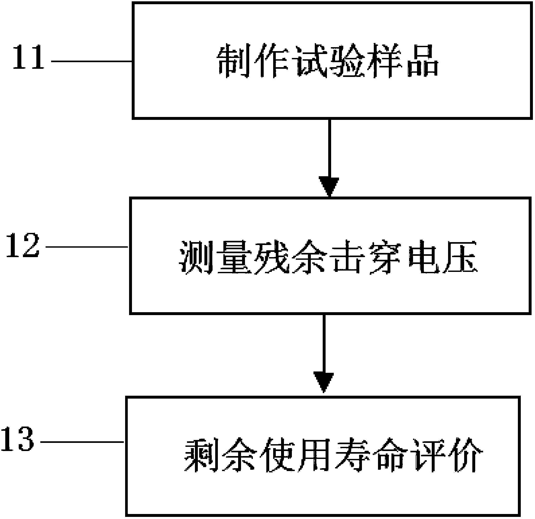
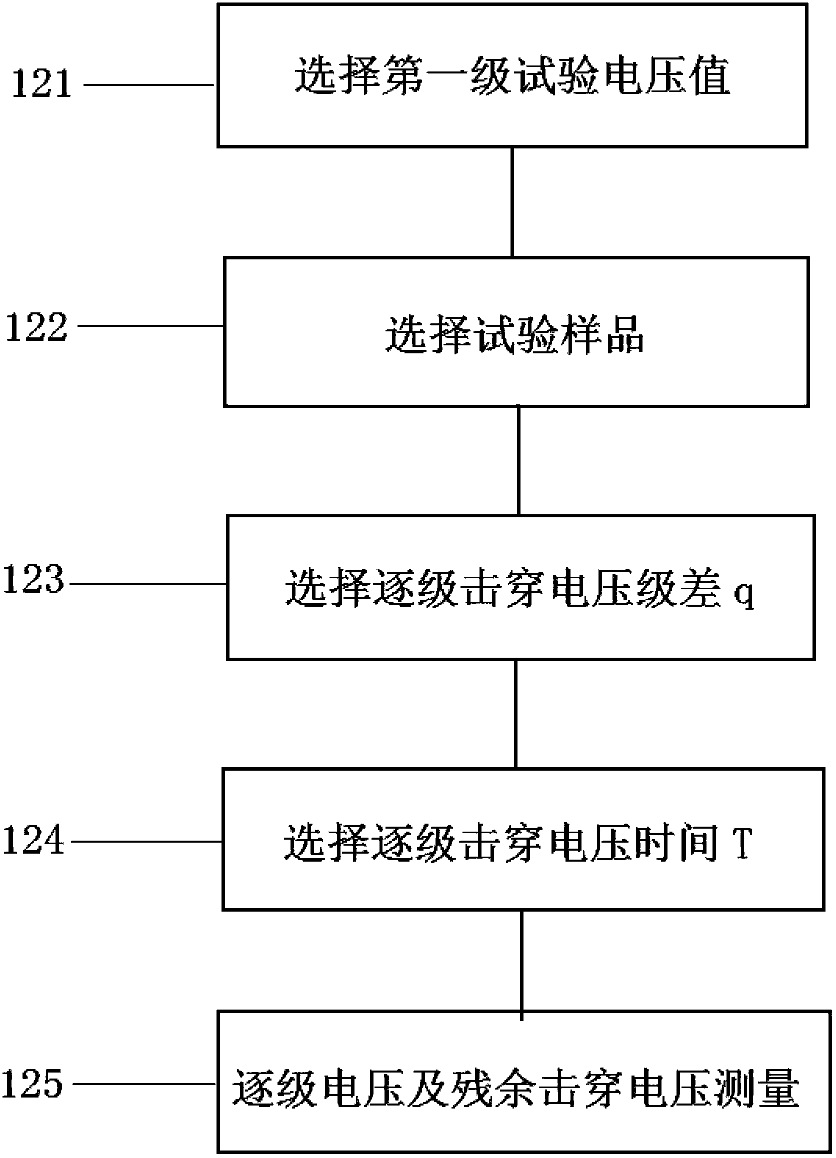
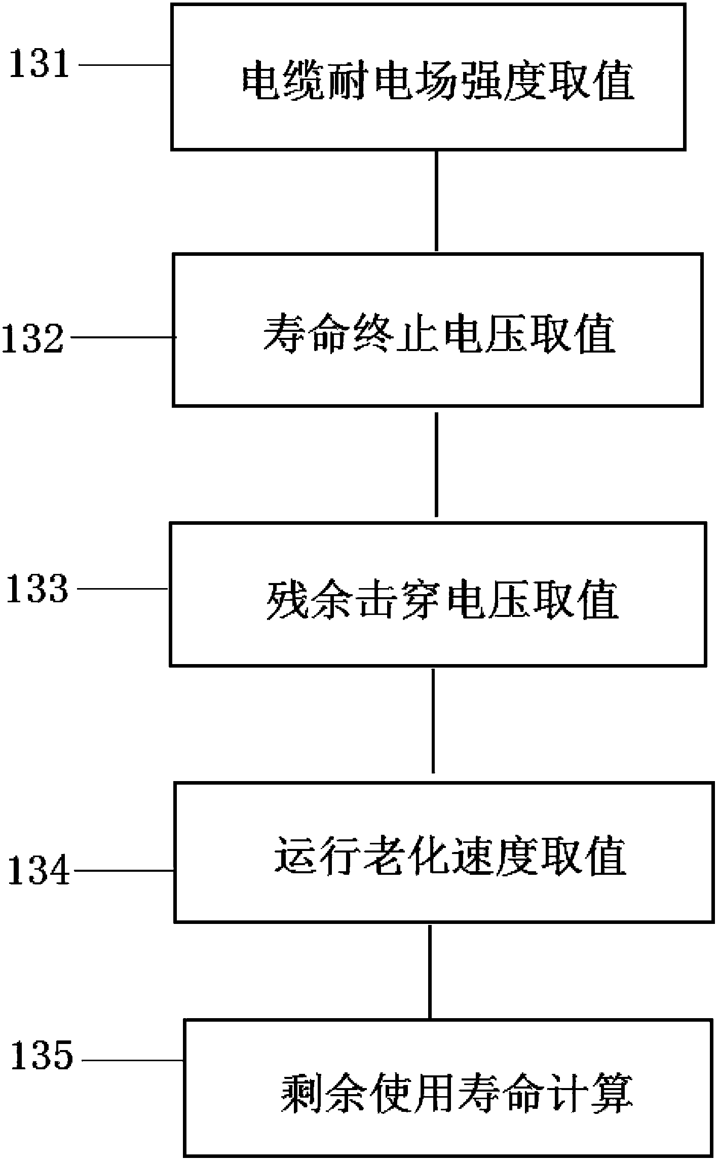
The invention discloses a crosslinked polyethylene cable residual life assessment method which comprises the following steps: residual breakdown voltage of a cable is obtained; and aging rate of the cable is calculated according to the cable aging rate formula of Sd=(H*E-Sy)/N, wherein Sd is aging rate, Sy is residual breakdown voltage of the cable, H is major insulation design thickness of the cable, E is major insulation design anti-electric field intensity and N is operational number of years of the cable; and residual useful life is calculated according to the residual useful life formula of SK=(H*E-SZ)/Sd-N, wherein SK is residual useful life of the cable and SZ is end-of-life voltage of the cable. The step of obtaining the residual breakdown voltage of the cable further comprises the following steps: major insulation resistance between each cable conductor and a copper mask tape is measured; power frequency voltage is applied between each cable conductor and the copper mask tape; and a power-frequency step-by-step breakdown voltage test is carried out so as to obtain the cable main insulation based residual breakdown voltage.

Description

technical field [0001] The invention relates to the technical field of cables, in particular to a method for evaluating the remaining life of a cross-linked polyethylene cable. Background technique [0002] The life prediction method of existing cables is mainly for newly manufactured cables. Under laboratory conditions, accelerated aging is used to simulate the remaining electric strength of the cable insulation in operation, so as to estimate the service life of the cable through different mathematical models. The following introduces Several cable life prediction methods in the prior art: [0003] (1) Non-destructive electrical performance test [0004] Research on the prediction of cable residual life was carried out relatively late in China, and research on the detection of weak points of XLPE cable insulation and aging detection technology began in foreign countries in the 1960s, and it is still developing. Japan is an early country that carried out research on the a...

Claims


Application Information

Patent Timeline
Patent Type & Authority Applications(China)
IPC IPC(8): G01R31/12
Inventor 李宇涛戴静旭
Owner BAOSHAN IRON & STEEL CO LTD
Why Eureka
Try Eureka