Membrane-electrode assembly for fuel cell, manufacturing method thereof, and solid polymer fuel cell using membrane-electrode assembly

A technology for electrode assemblies and fuel cells, which is applied in solid electrolyte fuel cells, fuel cell components, fuel cells, etc., and can solve problems such as unstable battery performance, deterioration, poor adhesion between conductive porous layer and catalyst layer, etc.

Inactive Publication Date: 2013-12-25
DAI NIPPON PRINTING CO LTD
View PDF8 Cites 6 Cited by
  • Summary
  • Abstract
  • Description
  • Claims
  • Application Information

AI Technical Summary

Problems solved by technology

[0005] However, conventional membrane-electrode assemblies use only fluorine-based resins with a high glass transition temperature as in Patent Documents 1 and 2. Therefore, the adhesion between the conductive porous layer and the catalyst layer is poor and the battery performance is unstable. question
In addition, in order to improve the adhesion, it is necessary to join at a high temperature of 260°C or higher. In the case of such a process, the ion-conductive polymer electrolyte contained in the catalyst layer and the resin constituting the electrolyte membrane will deteriorate. It has a bad influence on the performance of the battery, so it is actually difficult to join under such conditions

Method used


Image

  • Membrane-electrode assembly for fuel cell, manufacturing method thereof, and solid polymer fuel cell using membrane-electrode assembly
  • Membrane-electrode assembly for fuel cell, manufacturing method thereof, and solid polymer fuel cell using membrane-electrode assembly
  • Membrane-electrode assembly for fuel cell, manufacturing method thereof, and solid polymer fuel cell using membrane-electrode assembly

Examples


Embodiment 1

[0160] (i) The first conductive layer

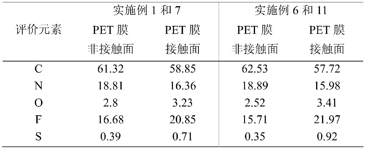
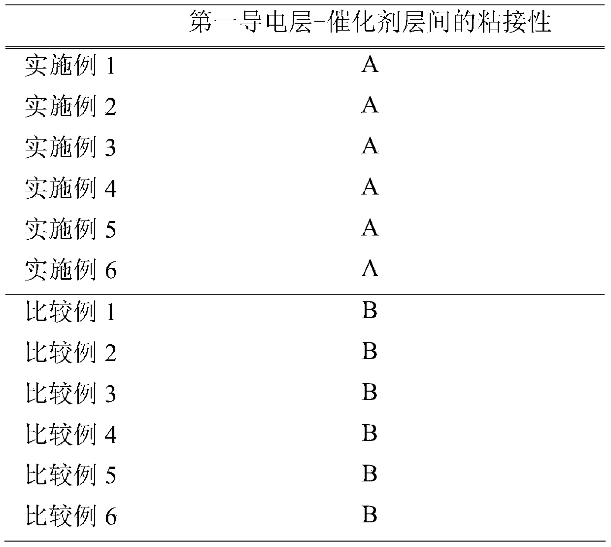
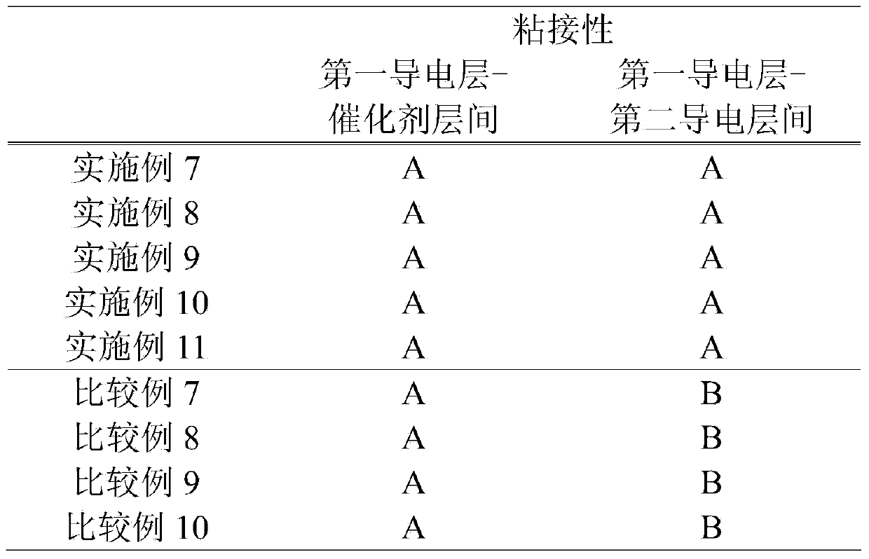
[0161] Disperse 100 parts by weight of conductive carbon particles, 50 parts by weight of fluororesin, 75 parts by weight of conductive carbon fiber (1), 1250 parts by weight of polymer (1) (62.5 parts by weight of solid content), 25 parts by weight of dispersant 350 parts by weight and 350 parts by weight of water were dispersed to prepare a paste composition for forming a first conductive layer. The paste composition for forming a first conductive layer was applied on a polyethylene terephthalate (PET) film on which a release layer was formed using an applicator so that the thickness became about 50 μm. Regarding the viscosity of this paste composition, the shear viscosity is a value of about 150 mPa·s at a shear rate of 1000 (1 / s). The method of measuring the viscosity of the paste composition was measured using hysica MCR301 manufactured by Anton Paar (as a jig, a conical jig with a diameter of 50 mm and an angle of 1° was used). I...

Embodiment 2

[0165] (i) The first conductive layer

[0166] Disperse 100 parts by weight of conductive carbon particles, 50 parts by weight of fluororesin, 75 parts by weight of conductive carbon fiber (1), 1250 parts by weight of polymer (1) (solid content 62.5 parts by weight), polymerize A paste composition for forming a first conductive layer was prepared by dispersing 200 parts by weight of the substance (2) (100 parts by weight of solid content), 25 parts by weight of a dispersant, and 350 parts by weight of water. This paste composition for first conductive layer formation was applied on the PET film on which the release layer was formed using an applicator so that the thickness became about 50 μm. Regarding the viscosity of this paste composition, the shear viscosity was a value of about 130 mPa·s at a shear rate of 1000 (1 / s). Then, it dried for about 15 minutes in the drying oven set at 95 degreeC, and produced the 1st conductive layer.

[0167] (ii) Membrane-electrode assembly...

Embodiment 3

[0170] (i) The first conductive layer

[0171]Disperse 100 parts by weight of conductive carbon particles, 50 parts by weight of fluororesin, 75 parts by weight of conductive carbon fiber (1), 1250 parts by weight of polymer (1) (solid content 62.5 parts by weight), polymerize A paste composition for forming a first conductive layer was prepared by dispersing 200 parts by weight of the substance (2) (100 parts by weight of solid content) and 350 parts by weight of water. This paste composition for first conductive layer formation was applied on the PET film on which the release layer was formed using an applicator so that the thickness became about 50 μm. Regarding the viscosity of this paste composition, the shear viscosity was a value of about 130 mPa·s at a shear rate of 1000 (1 / s). Then, it dried for about 15 minutes in the drying oven set at 95 degreeC, and produced the 1st conductive layer.

[0172] (ii) Membrane-electrode assembly

[0173] The first conductive layer ...


PUM

PropertyMeasurementUnit
particle sizeaaaaaaaaaa

Abstract

By layering a gas expansion layer, which has a first conductive layer comprising a specific conductive carbon material and a specific high molecular weight polymer, on a catalyst layer in such a way that the catalyst layer and the first conductive layer are in contact and the high molecular weight polymer in the first conductive layer is present with greater density at the surface in contact with the catalyst layer than at the surface not in contact with the catalyst layer, it is possible to provide a membrane-electrode assembly having strong adhesion between the catalyst layer and gas expansion layer. In addition, by further employing a gas expansion layer, which has a second conductive layer comprising a specific conductive carbon material and a specific high molecular weight polymer, on the first conductive layer and layering the gas expansion layer on the catalyst layer in such a way that the high molecular weight polymer in the first conductive layer is present with greater density at the surface in contact with the catalyst layer than at the surface in contact with the second conductive layer and the high molecular weight polymer in the second conductive layer is present with greater density at the surface in contact with the first conductive layer than at the surface not in contact with the first conductive layer, it is possible to provide a membrane-electrode assembly for a fuel cell that suppresses positional offset between the catalyst layer and a conductive porous layer and between the conductive porous layer and a conductive porous base material.

Description

technical field [0001] The present invention relates to a membrane-electrode assembly for a fuel cell, a method for producing the same, and a polymer electrolyte fuel cell using the membrane-electrode assembly. Background technique [0002] A membrane-electrode assembly (MEA) constituting a polymer electrolyte fuel cell has a structure in which a gas diffusion layer, a catalyst layer, an ion-conducting solid polymer electrolyte membrane, a catalyst layer, and a gas diffusion layer are laminated in this order. [0003] The reaction of the polymer electrolyte fuel cell proceeds at the three-phase interface where the catalyst particles, the electrolyte, and the fuel gas in the catalyst layer are in contact. In order to obtain high power generation performance, the moisture generated by the electrode reaction at the three-phase interface is efficiently discharged to the outside of the electrode system, so that the fuel gas is supplied without delay, and the supplied fuel gas is ...

Claims


Application Information

Patent Timeline
Patent Type & Authority Applications(China)
IPC IPC(8): H01M8/02H01M4/86H01M4/88H01M8/10
CPCH01M4/8642H01M4/881H01M8/0234H01M8/0239H01M8/0241H01M8/0243H01M8/0297H01M8/1004H01M2008/1095Y02E60/50Y02P70/50
Inventor 竹内直也岸本比吕志
Owner DAI NIPPON PRINTING CO LTD
Why Eureka
Try Eureka