
Ultrasonic-vibration micro electric discharge machining workbench

A technology of ultrasonic vibration and electric discharge, applied in the field of micro electric discharge machining, can solve the problems of difficult chip removal in micro holes or special-shaped holes, unsuitable for micro electric discharge machining, and difficult discharge of electric erosion products, so as to facilitate transfer and promote discharge , the effect of increasing stability

Inactive Publication Date: 2014-01-01
SHANDONG UNIV
View PDF5 Cites 10 Cited by
  • Summary
  • Abstract
  • Description
  • Claims
  • Application Information

AI Technical Summary

Problems solved by technology

Due to the small processing scale, fine tool electrodes, small discharge pulse energy and small discharge gap, the regular retreat flushing and chip removal method in traditional EDM is no longer suitable for micro-EDM, which makes it difficult for electro-erosion products to be discharged from the processing area. Especially for micro-holes with high depth-to-diameter ratio or special-shaped holes, it is more difficult to remove chips, prone to short-circuit and arcing, and the processing efficiency is extremely low

Method used


Image

  • Ultrasonic-vibration micro electric discharge machining workbench

Examples


Embodiment 1

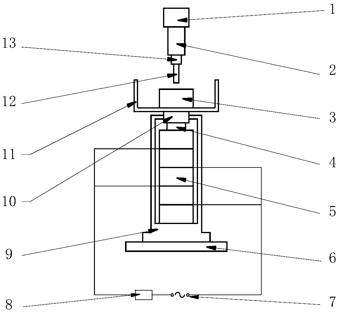
[0015] Such as figure 1 As shown, the present invention is an ultrasonic vibration micro-EDM workbench based on a micro-EDM machine tool, including a preload spring 4, a piezoelectric ceramic 5, a machine tool base 6, a power supply 7, an adjustable resistor 8, a piezoelectric Actuator housing 9, push rod 10, working fluid tank 11. When the mass of the processed workpiece 3 is small, the dynamic follow-up effect is better. The ultrasonic vibration micro-EDM workbench can adopt high-frequency ultrasonic vibration, and the frequency range is 38KHz-42KHZ. The processed workpiece is fixed in the working fluid tank 5 by bolts. And immersed in the working fluid, the processing effect is better. The number of laminated piezoelectric ceramics 5 is three. The piezoelectric actuator housing 9 plays the role of protecting the piezoelectric ceramic 5 and is made of corrosion-resistant stainless steel. The specific size is determined according to the size of the piezoelectric ceramic 5 a...

Embodiment 2

[0021] Such as figure 1 As shown, when performing rough machining, the number of laminated piezoelectric ceramics 5 is five, so as to obtain greater machining efficiency. Others are the same as embodiment one.

Embodiment 3

[0023] Such as figure 1 As shown, when the workpiece 3 is small in size, it is difficult to fix it mechanically. The workpiece 3 is glued and fixed in the working fluid tank 5 and immersed in the working fluid. After processing, the workpiece is dissolved by an organic solvent to remove it. Others are the same as embodiment one.


PUM


Abstract

The invention relates to an ultrasonic-vibration micro electric discharge machining workbench which comprises a machine tool base 6, a power source 7, an adjusting resistor 8 and a working liquid tank 11. The ultrasonic-vibration micro electric discharge machining workbench is characterized by further comprising a pre-tightening spring 4, piezoelectric ceramic 5, a piezoelectric actuator shell 9 and a pushing rod 10; an overlying and combining form is adopted to parallelly connecting the piezoelectric ceramic 5 mutually in a circuit; the piezoelectric ceramic 5 serving as a micro-vibration exciting component converts electric energy into mechanical vibration energy; under the action of voltage, by utilizing the inverse piezoelectric effect of the piezoelectric ceramic, the piezoelectric ceramic drives the working surface to extend or shorten. During electric discharge machining, by utilizing ultrasonic vibration of a workpiece, the circulating state of working liquid is effectively improved, discharging of an electric corrosion product is promoted, stability of the machining process is improved, the phenomena like shorting-out and arcing can be automatically eliminated, and the ultrasonic-vibration micro electric discharge machining workbench is especially suitable for micro deep hole and deep groove machining.

Description

Technical field: [0001] The invention belongs to the technical field of micro electric discharge machining, and relates to an ultrasonic vibration micro electric discharge machining workbench. Background technique: [0002] Due to the advantages of simple equipment, good controllability, no cutting force, and strong applicability, the micro-EDM technology has great advantages in the processing of micro-scale parts, and has great advantages in the micro-processing of micro-devices. application potential. At present, a variety of micro-EDM machine tools have been put into use in the industry. The micro-EDM machine tool MG-ED82W developed and produced by Matsushita Seiki in Japan adopts RC micro-energy relaxation pulse power supply, and through the timing return of the tool electrode, It can stably process micro-holes and narrow grooves with a scale of 10 μm. Domestically, Nanjing University of Aeronautics and Astronautics has successfully processed a For micro holes, the I...

Claims


Application Information

Patent Timeline
IPC IPC(8): B23H7/38
Inventor 张勤河张敏张覃婧
Owner SHANDONG UNIV
Learn More