Boiler-turbine coupled flue gas waste heat utilization system capable of preheating air based on condensed water

A technology of flue gas waste heat and preheating air, applied in the directions of preheating, feed water heater, steam boiler, etc., can solve the problems of no consideration of restrictions, single form, low temperature sulfuric acid dew point corrosion, etc., achieving significant economic benefits and functional ability low effect

Inactive Publication Date: 2014-01-01
NORTH CHINA ELECTRIC POWER UNIV (BAODING)
View PDF5 Cites 17 Cited by
  • Summary
  • Abstract
  • Description
  • Claims
  • Application Information

AI Technical Summary

Problems solved by technology

[0003] At present, it is suitable to use the waste heat of flue gas at the tail of the boiler to directly consider using the low-temperature flue gas at the outlet of the air preheater to heat the condensed water. Since the exhaust gas temperature of the air preheater is about 120-140°C, when the temperature of the heating surface reaches the acid dew point Low-temperature sulfuric acid dew point corrosion will occur when the temperature is low, so the temperature utilization space is limited and the form is single
And it does not take into account the constraints brought by the structural arrangement of the heating surface at the rear of the boiler to the utilization of waste heat of the flue gas, so that the waste heat resources of the flue gas cannot be effectively utilized in an optimized form

Method used


Image

  • Boiler-turbine coupled flue gas waste heat utilization system capable of preheating air based on condensed water
  • Boiler-turbine coupled flue gas waste heat utilization system capable of preheating air based on condensed water

Examples


Embodiment Construction

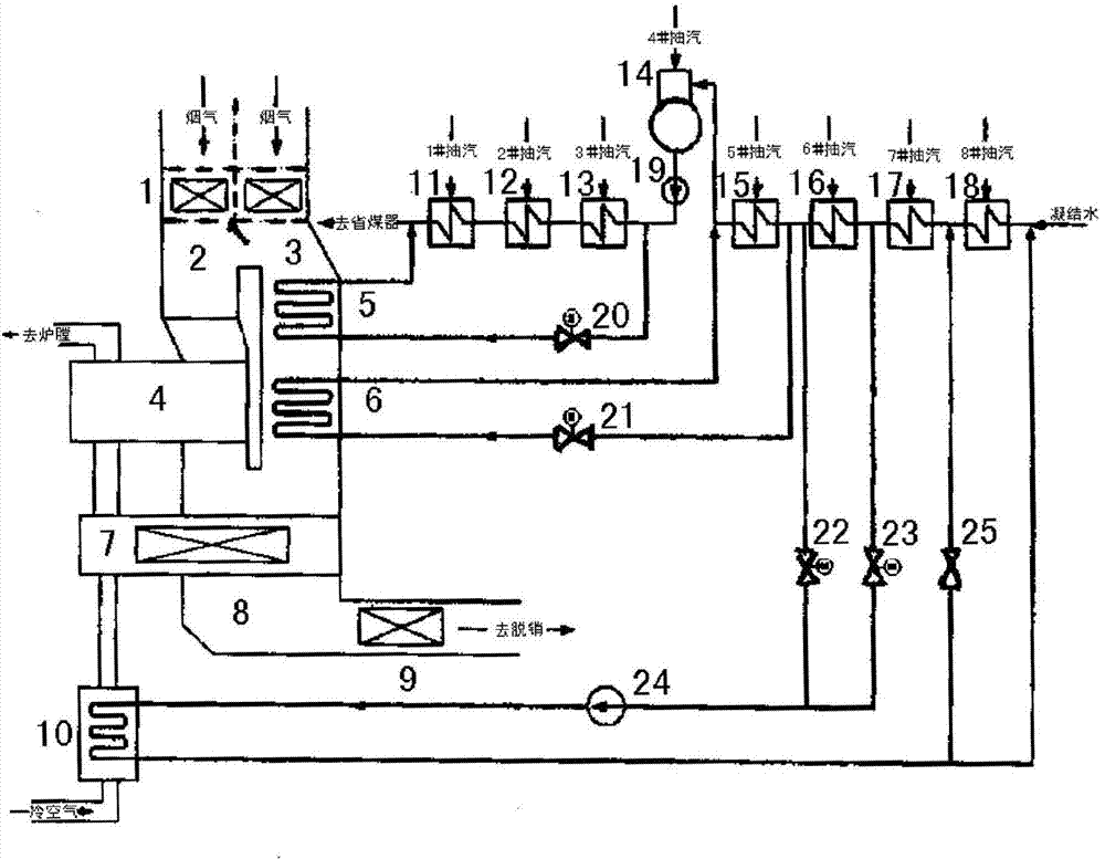
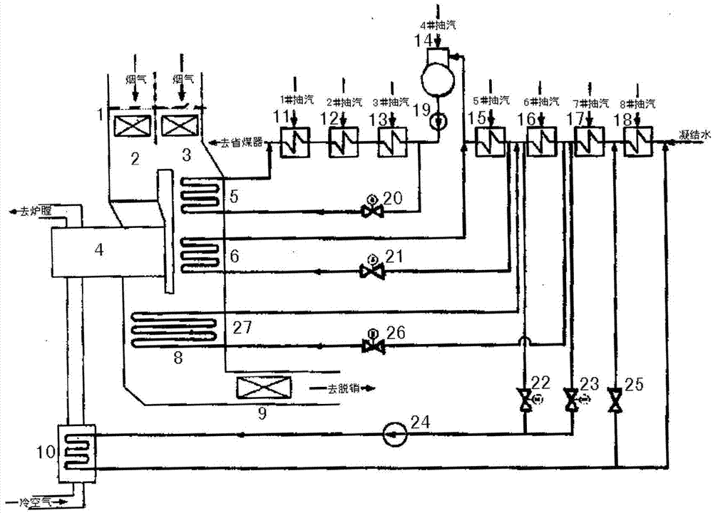
[0016] The invention proposes a waste heat utilization system of flue gas coupled with a machine furnace based on condensed water preheating air. The following will be described in conjunction with the accompanying drawings and examples.

[0017] Such as figure 1 In the schematic diagram of the machine-furnace coupled flue gas waste heat utilization system based on condensed water preheating air shown, after the main flue 2 and the bypass flue 3 are connected in parallel, the upper end is connected to the main economizer 1, and the lower end is connected to the confluent flue 8 , the first-stage smoke-water heat exchanger 5 and the second-stage smoke-water heat exchanger 6 are set in turn in the bypass flue 3, and the flue gas-air heater 7 is set in the confluent flue 8; the main air preheater 4 Connect the combined flue 8, the main flue 2 and the flue gas-air heater 7 respectively; the air side of the flue gas-air heater 7 is respectively connected to the condensate-air heat...


PUM


Abstract

The invention discloses a boiler-turbine coupled flue gas waste heat utilization system capable of preheating air based on condensed water, which belongs to the field of energy conservation of electric stations. The boiler-turbine coupled flue gas waste heat utilization system mainly comprises a main economizer, a main flue, a bypass flue, a confluence flue, a main air preheater, smoke water heat exchangers, a high-pressure heater, a low-pressure heater, a deaerator, a flue gas-air heater and a condensed water-air heater. Cold air is preheated by extracting low-temperature condensed water in some of thermodynamic systems and low-temperature flue gas of a boiler through utilizing the condensed water-air heater; a primary smoke water heat exchanger and a secondary smoke water heat exchanger are used for heating the feeding water and the condensed water so as to replace extraction steam, with higher pressure, of a steam turbine. According to the flue gas waste heat utilization system, waste heat is effectively utilized, and the air is preheated by utilizing the low-level condensed water and the low-temperature flue gas of the boiler, so that the high-pressure extraction steam used for heat return is saved, thus work of a machine set is remarkably increased, and deep energy conservation and consumption reduction of a coal-fired generator set can be realized; furthermore, a problem of low-temperature corrosion of a waste heat utilization heating surface is relieved, and remarkable economic benefit is obtained.

Description

technical field [0001] The invention belongs to the field of energy saving and emission reduction, and particularly relates to a system for utilizing waste heat of machine-furnace coupled flue gas based on condensed water preheating air. The air is preheated, and the preheated air enters the main air preheater to be further heated to the required temperature; (2) The flue gas from the outlet of the boiler economizer enters the first air preheater and the bypass flue at the same time , The second-stage smoke-water heat exchanger, the outlet flue gas passes through the flue gas-air heater, and then enters the dust removal and desulfurization device; (3) The first-stage smoke-water heat exchanger can be used to heat the turbine feed water and replace part of the high pressure For steam extraction, the second-stage smoke-water heat exchanger can also be used to heat condensed water at a higher temperature and replace higher-pressure extraction steam. Background technique [000...

Claims


Application Information

Patent Timeline
Patent Type & Authority Applications(China)
IPC IPC(8): F22D1/38F22B31/08F23L15/00
CPCY02E20/34
Inventor 徐钢刘超杨勇平韩宇杨志平黄圣伟许诚
Owner NORTH CHINA ELECTRIC POWER UNIV (BAODING)
Why Eureka
Try Eureka