Micro-domain laser probe component analyzer based on optical fiber waveguide

A technology of laser probe and component analysis, which is applied in the direction of material excitation analysis, etc., can solve the problems of large beam quality interference, poor flexibility of optical path system, and difficult lens manufacturing, so as to reduce volume and space occupancy and save on equipment. Accurate and adjusted time, good effect of coaxial excitation

Active Publication Date: 2014-01-15
HUAZHONG UNIV OF SCI & TECH
View PDF10 Cites 16 Cited by
  • Summary
  • Abstract
  • Description
  • Claims
  • Application Information

AI Technical Summary

Problems solved by technology

However, due to the large laser pulse energy (>100mJ) and the large diameter of the focused spot (>100um) used in the traditional LIBS technology, it is impossible to conduct accurate quantitative and qualitative analysis of the elements in the micro-area of ​​the material, resulting in the recent years. Laser probe technology is gaining more and more attention
However, the micro-area laser probe technology still has the following two main deficiencies: 1. The detection limit is low; 2. The system is greatly disturbed by the outside world, resulting in low detection accuracy and poor stability.
However, the device still has the following deficiencies: First, the device uses mirrors and half-mirrors to realize the coaxial transmission of two laser beams. Maintenance, and the lens manufacturing is difficult and costly; second, the equipment uses a mirror system to transmit the laser beam to the sample surface, the optical path system has poor flexibility, and the beam quality is greatly affected by external noise and interference; third, the optical path of the equipment The system is designed for a specific laser wavelength, and the versatility of the equipment is poor. To use another laser wavelength, the optical path system must be replaced and re-adjusted. The process is cumbersome and time-consuming.

Method used


Image

  • Micro-domain laser probe component analyzer based on optical fiber waveguide
  • Micro-domain laser probe component analyzer based on optical fiber waveguide
  • Micro-domain laser probe component analyzer based on optical fiber waveguide

Examples


Embodiment Construction

[0025] The specific embodiments of the present invention will be further described below in conjunction with the accompanying drawings. It should be noted here that the descriptions of these embodiments are used to help understand the present invention, but are not intended to limit the present invention. In addition, the technical features involved in the various embodiments of the present invention described below can be combined with each other as long as they do not constitute a conflict with each other.

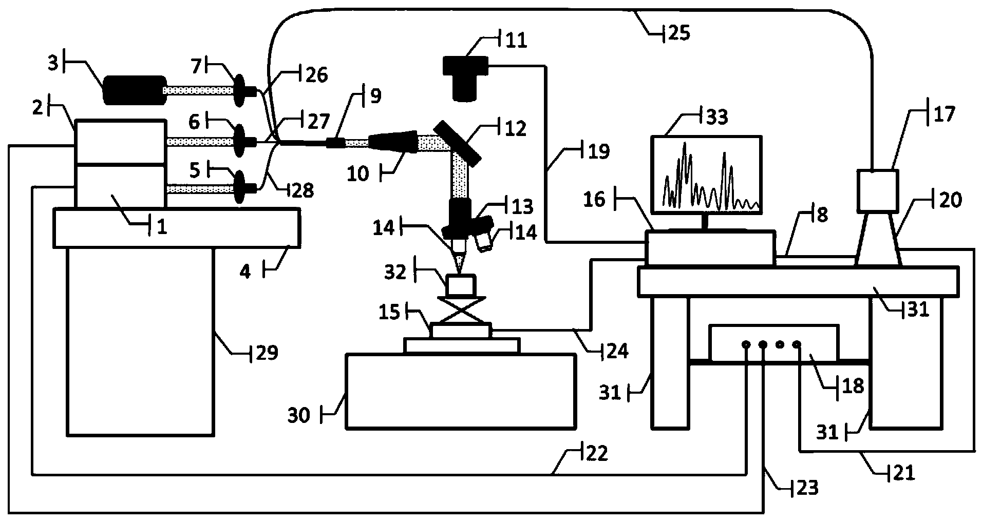
[0026] Such as figure 1 As shown, the laser probe instrument provided by the first specific embodiment includes a Nd:YAG laser 1, a wavelength tunable laser 2, an LED light source 3, an optical platform 4, a first fiber coupler 5, a second fiber coupler 6, The third optical fiber coupler 7, data line 8, fiber optic collimator 9, beam expander 10, CCD monitoring camera 11, broadband dielectric film mirror 12, objective lens converter 13, focusing objective lens 14, displ...


PUM


Abstract

The invention discloses a micro-domain laser probe component analyzer based on optical fiber waveguide. The analyzer comprises a Nd:YAG laser, a wavelength-tunable laser, a CCD monitoring camera, a computer, a grating spectrometer, a focusing objective lens, a displacement platform, a digital delay pulse generator, and an enhanced CCD. The focusing lens is a reflective focusing lens. The Nd:YAG laser and the wavelength-tunable laser both adopt optical fiber waveguide for carrying out laser pulse transmission; laser pulse is collimated by using an optical fiber collimator and expanded by a beam expander, and enters the focusing objective lens. Laser pulse transmitted by the Nd:YAG laser burns a surface micro-domain on a sample to be analyzed, such that plasma is formed; the laser pulse transmitted by the wavelength-tunable laser is applied on the plasma, such that resonance excitation is caused; one end of the optical fiber is used for collecting spectral signal transmitted by the plasma, and the other end is connected with an optical fiber interface of the grating spectrometer. According to the invention, precise qualitative and quantitative analysis of laser probe upon substance micro-domain components can be realized.

Description

technical field [0001] The invention belongs to the technical field of component analysis and detection, and specifically relates to a micro-area laser probe component analyzer based on an optical fiber waveguide, which is mainly used for precise deterministic and quantitative analysis of material components in micro-regions. Background technique [0002] Laser probe technology, that is, Laser-Induced Breakdown Spectroscopy (LIBS for short) technology, is to use high-energy laser beams to bombard the surface of the analyzed material to generate plasma, and collect the characteristic spectrum emitted by the plasma and analyze it. It is a new type of material composition analysis technology to obtain the type and content of elements contained in the analyzed substance. LIBS technology has the advantages of no need for sample pretreatment, simultaneous detection of multiple elements, and online and real-time detection. It has been widely concerned since its birth. However, due...

Claims


Application Information

Patent Timeline
Patent Type & Authority Applications(China)
IPC IPC(8): G01N21/63
Inventor 李祥友王旭朝郑重沈萌郭连波曾晓雁
Owner HUAZHONG UNIV OF SCI & TECH
Why Eureka
Try Eureka