
Metal grid type transparent conducting thin film and manufacturing method thereof

A technology of transparent conductive film and metal grid, which is applied in the direction of cable/conductor manufacturing, conductive layer on insulating carrier, circuit, etc., to achieve the effect of excellent conductive performance

Inactive Publication Date: 2014-01-29
BEIJING INSTITUTE OF GRAPHIC COMMUNICATION
View PDF6 Cites 2 Cited by
  • Summary
  • Abstract
  • Description
  • Claims
  • Application Information

AI Technical Summary

Problems solved by technology

However, the metal grid type transparent conductive film is mainly prepared by etching, silver salt method or nanoimprinting method, and there are few reports on the method prepared by traditional printing method.
However, these traditional printing methods have shortcomings of one kind or another. For example, the maximum printing accuracy obtained by gravure printing is currently about 50 μm, and the thickness of the film layer is 5 μm; the maximum accuracy of screen printing is about 100 μm, and the thickness of the film layer is dozens. μm

Method used


Image

  • Metal grid type transparent conducting thin film and manufacturing method thereof
  • Metal grid type transparent conducting thin film and manufacturing method thereof
  • Metal grid type transparent conducting thin film and manufacturing method thereof

Examples


Embodiment 1

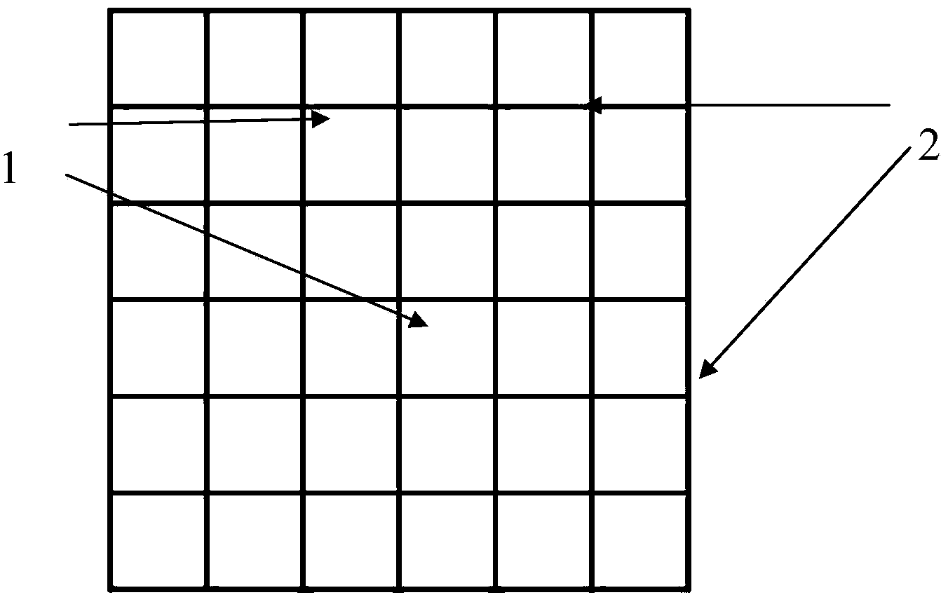
[0047] figure 1 It is a schematic diagram of the principle of the metal grid type transparent conductive film of the present invention; wherein, 1 is a blank space, and 2 is a metal silver conductive grid.

[0048] Such as figure 2 As shown, it is a schematic cross-sectional structure diagram of the metal conductive grid printing plate of the first embodiment; wherein the protruding part is the grid relief width of the printing plate. Among them, 3 is the grid relief height of the printing plate, 4 is the graphic part, and 5 is the blank part. The printing plate grid of the metal conductive grid is a square array, the side length of the square is 400 μm, and the relief width d of the printing plate grid is 17.8 μm. The printing material used is a commercially available flexible transparent PET with a thickness of 88 μm and a light transmittance of a=91%.

[0049] image 3 The scanning electron microscope image of the metal grid-type transparent conductive film prepared fo...

Embodiment 2

[0072] Others are the same as in Example 1, except that the nano-silver is changed to nano-copper.


PUM

PropertyMeasurementUnit
thicknessaaaaaaaaaa
thicknessaaaaaaaaaa
thicknessaaaaaaaaaa

Abstract

The invention relates to a metal grid type transparent conducting thin film and a manufacturing method thereof. The metal grid type transparent conducting thin film comprises a substrate and a metal layer, wherein the metal layer is a patterned metal conducting grid. The sum of the areas of the positions except for the metal conducting grid is more than 80% of the overall area of the thin film. According to the metal grid type transparent conducting thin film, grid patterns are printed on the flexible transparent substrate through conductive ink in a flexographic printing mode, and batch production is achieved in a reel-to-reel high-efficiency producing mode; meanwhile the flexographic printing mode not only guarantees that the metal grid type transparent conducting thin film has excellent photoelectric performance, but also guarantees that the thickness of the ink lay of the grid is smaller than 1 micron, excellent conductive performance is obtained, lines are flat, and surface flatness of the transparent conducting thin film is also improved.

Description

technical field [0001] The invention relates to a transparent conductive film and a preparation method thereof, in particular to a metal grid type transparent conductive film and a preparation method thereof. Background technique [0002] Transparent conductive film is a film with good electrical conductivity and high light transmittance in the visible light wavelength range. It is an indispensable and important functional material for touch screens, OLED displays, OLED lighting, thin-film solar cells, e-books, transparent electromagnetic wave shielding, etc., and has an extremely broad market space. [0003] ITO (Indium tin oxide indium tin oxide) transparent conductive film has excellent light transmission and conductivity, so that ITO transparent conductive film has always dominated the market of transparent conductive film. [0004] At present, the technology of preparing transparent conductive film has traditional evaporation technology, but the transparent conductive ...

Claims


Application Information

Patent Timeline
Patent Type & Authority Applications(China)
IPC IPC(8): H01B5/14H01B13/00
Inventor 王瑜莫黎昕冉军李路海高荟蓉
Owner BEIJING INSTITUTE OF GRAPHIC COMMUNICATION
Learn More