Ultraviolet detector manufacturing method

An ultraviolet detector and ultraviolet technology, applied in the field of photoelectric detection, can solve the problems of single wavelength response, serious problem of thin film phase separation, etc., and achieve the effect of reducing thermal effect

Inactive Publication Date: 2013-12-11
JIANGSU UNIV
View PDF3 Cites 23 Cited by
  • Summary
  • Abstract
  • Description
  • Claims
  • Application Information

AI Technical Summary

Problems solved by technology

[0003] In the study of ZnO-based ultraviolet detection, the more prominent progress is focused on the design and preparation of thin-film devices. People combine energy band engineering design and use a variety of thin-film technologies to prepare Mg 1-x Zn x O alloy materials, constructing ultraviolet detectors with different structures such as Schottky, p-n, p-i-n, etc., have made a meaningful discussion on the photoelectric response characteristics of the visible blind area and even the solar blind area; although theoretically, Mg x Zn 1-x The bandgap of O can be adjusted from 3.3 to 7.8 eV, which is expected to achieve a wide range of ultraviolet detection from 160 to 380 nm, but Mg 1-x Zn x The phase separation problem in O thin films is serious, the crystal quality needs to be improved, and p-type doping is a well-known bottleneck problem
[0004] At the same time, ZnO nanowires with high specific surface area and excellent crystallinity provide a good material basis for the construction of high-sensitivity ultraviolet detection devices; There are obvious advantages, but the device manufacturing process mostly adopts the "pick and place" method, and the reported detection range is mainly in the visible blind area, and mostly responds to a single wavelength

Method used


Image

  • Ultraviolet detector manufacturing method
  • Ultraviolet detector manufacturing method
  • Ultraviolet detector manufacturing method

Examples


Embodiment Construction

[0023] The following is a description of the specific implementation of the preparation of ZnO quantum dots in the present invention and the preparation of ultraviolet detection devices by gradient assembly in multi-layer graphene using it as an ultraviolet photoelectric response active material.

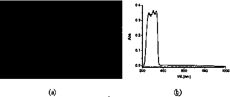
[0024] figure 1 (a) The ZnO quantum dots in (a) are prepared by colloid chemical method, and can also be prepared by other methods, but the size is required to be from large to small, and the absorption wavelength can be adjusted from near ultraviolet to deep ultraviolet (380-275nm), and It has good dispersibility; the specific preparation process of zinc oxide quantum dots in this example is as follows: dissolve 0.01 mol of zinc acetate in 100 mL of absolute ethanol and reflux at 80 ° C for 3 h as a precursor, then cool it to room temperature, and then Dissolve 0.01mol sodium hydroxide in 100mL absolute ethanol, slowly add the sodium hydroxide ethanol solution to the precursor, and...


PUM


Abstract

The invention belongs to the technical field of photoelectric detection, and particularly discloses an ultraviolet detector manufacturing method which is achieved by gradient assembly of multi-size zinc oxide quantum dots in multiple layers of graphene. According to the ultraviolet detector manufacturing method, structure and performance advantages of the ZnO quantum dots and the graphene are combined, and collochemistry is adopted as the basic method to obtain the ZnO quantum dots with different sizes, and the band gaps of the ZnO quantum dots vary from the near ultraviolet area to the deep ultraviolet area; wet chemistry is adopted to prepare single-layer oxidized graphene, carboxyl functional group modification is then carried out on the surface of the single-layer oxidized graphene so that ZnO quantum dots with a single size can be suitable for being assembled on the surface of the single-layer oxidized graphene, and then the ZnO quantum dots (QD) with different sizes are used as active materials of ultraviolet response to construct a multi-layer sandwich type structure. According to the ultraviolet detector manufacturing method, gold, or platinum or ITO is used as electrode materials, a horizontal distribution type strip-shaped or itnerdigital electrode structure is designed, and then an ultraviolet detector is obtained and inter-band absorption response from near ultraviolet to deep ultraviolet is achieved.

Description

technical field [0001] The invention belongs to the technical field of photoelectric detection, in particular to a preparation method for constructing an ultraviolet detection device by gradient assembly of multi-size zinc oxide quantum dots in multi-layer graphene. Background technique [0002] Ultraviolet detection is an important dual-use photoelectric detection technology for both military and civilian purposes. It has a wide range of applications in flame and missile plume monitoring, space communication, organic pollution and ozone monitoring, chemical and biological analysis, etc. Silicon-based, it needs to filter the incident visible light and infrared light and needs to be equipped with cooling components; compared with this, wide-bandgap semiconductors with band gaps in the ultraviolet region, such as SiC, diamond, GaN and ZnO, etc., naturally avoid silicon These problems of the detector; among them, the band gap of ZnO at room temperature is about 3.37eV, and the ...

Claims


Application Information

Patent Timeline
Patent Type & Authority Applications(China)
IPC IPC(8): H01L31/18H01L31/101B82Y10/00H01L31/0264
CPCY02P70/50
Inventor 吴春霞张双鸽周明宋泽琳
Owner JIANGSU UNIV
Why Eureka
Try Eureka