
Rapid circulation air cooling vacuum furnace

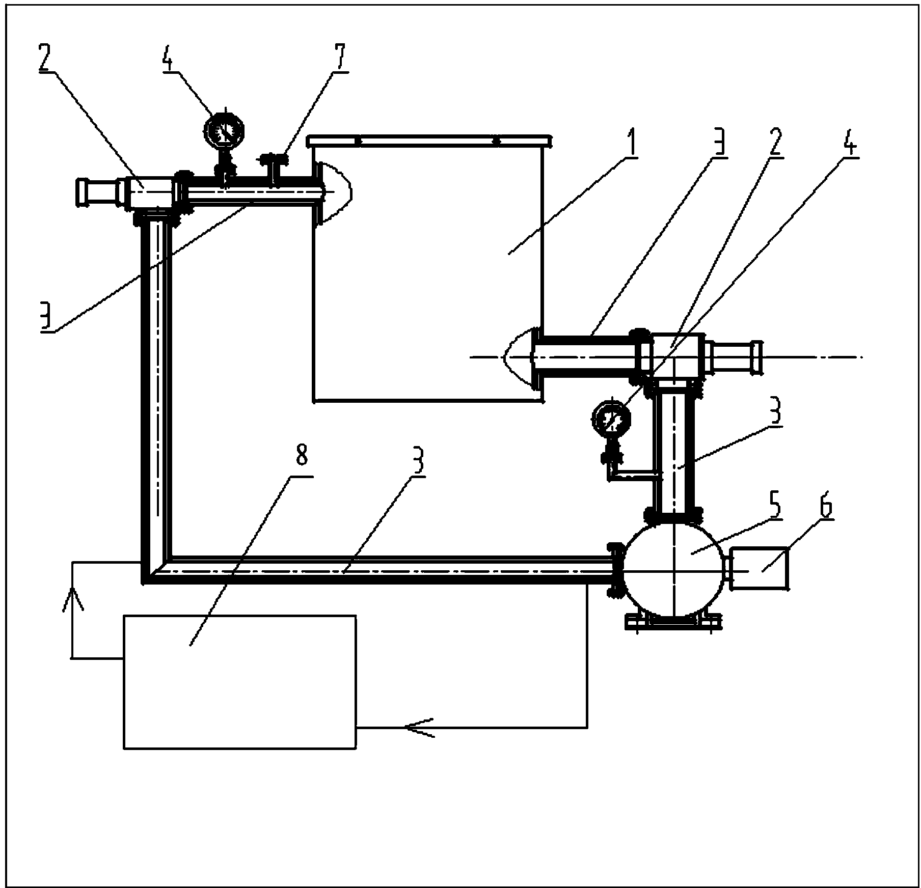
A rapid cycle, vacuum furnace technology, used in furnaces, furnace cooling, furnace components, etc., can solve problems affecting processing quality, furnace cavity size and process limitations, waste of inert gas, etc., to achieve a wide annealing process range and wide use conditions , Air cooling effect uniform effect

Active Publication Date: 2014-02-05
BEIJING TECHNOL SCI
View PDF15 Cites 10 Cited by
  • Summary
  • Abstract
  • Description
  • Claims
  • Application Information

AI Technical Summary

Problems solved by technology

However, the size of the material is limited, and the opening and closing process of the cooling chamber will affect the processing quality of the material in the furnace chamber to a certain extent.
In addition, the temperature and chamber pressure cannot be accurately controlled when gas quenching is used for materials that cannot be water quenched or oil quenched.
Chinese patent CN201110125236.4 also designed a similar cooling scheme, and added circulating water cooling to the chamber wall and screen door, but similarly, there are also disadvantages such as uncontrollable chamber pressure during air cooling
[0006] But in general, although the way of separating the furnace chamber into a heating chamber and a cooling chamber can improve the efficiency of the vacuum furnace to a certain extent, the multi-chamber and water-cooling design has limited application range, no energy saving and impact Processing quality and other shortcomings; and the air cooling design has great restrictions on the size and process of the furnace chamber, which not only wastes a lot of inert gas, but also easily affects the stability of the workpiece quality

Method used


Image

  • Rapid circulation air cooling vacuum furnace
  • Rapid circulation air cooling vacuum furnace

Examples


Embodiment 1

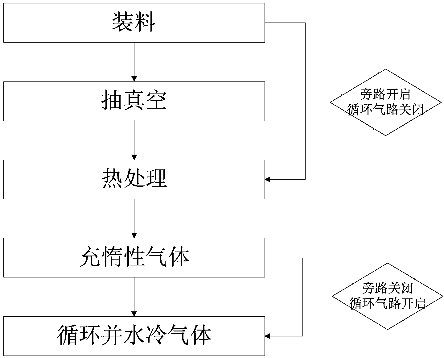
[0039] After the CVD diamond is annealed from 1100°C to 500°C in a fast-circulating air-cooled vacuum furnace, the bypass is closed, and a hydrogen-argon gas mixture is introduced until the chamber pressure is 3.0KPa. Turn on the rapid cycle air cooling system and turn on the water cooling device. Adjust the frequency conversion motor and water cooling device to make the system reduce the temperature of CVD diamond from 500°C to below 100°C within 15 minutes.

Embodiment 2

[0041] After the tungsten carbide powder compact is sintered at 1400°C in a fast-circulating air-cooled vacuum furnace, the bypass is closed and hydrogen gas is introduced until the chamber pressure is 0.5KPa. Turn on the rapid cycle air cooling system and turn on the water cooling device. Adjust the frequency conversion motor and water cooling device to make the system reduce the temperature of the cemented carbide blank from 1400°C to 700°C within 2 hours. Continue to feed hydrogen until the chamber pressure is 2KPa, adjust the frequency conversion motor and water cooling device, and the system will reduce the temperature of the cemented carbide blank from 700°C to below 100°C within 30 minutes.


PUM


Abstract

The invention relates to a rapid circulation air cooling vacuum furnace which comprises a rapid circulation air cooling vacuum furnace body and a rapid circulation air cooling system thereof. The rapid circulation air cooling vacuum furnace is applied to the field of materials and machinery. A roots pump, a variable-frequency motor and a water cooling system are serially connected with the vacuum furnace body to form a circulation air path, rarefied gas can continuously and uniformly circulate in the vacuum furnace body with any size and in any shape by the aid of high compression ratio of the roots pump under low pressure, and materials in the vacuum furnace body can be rapidly cooled through water cooling devices on two sides. The use range and the use efficiency of the rapid circulation air cooling vacuum furnace are greatly increased, control ranges and accuracy of the temperature and the pressure of the vacuum furnace are improved, and temperature uniformity of a plurality of workpieces is improved.

Description

technical field [0001] The invention relates to a fast-circulation air-cooled vacuum furnace, in particular to a rapid-circulation air-cooling system of the vacuum furnace. Background technique [0002] A vacuum furnace is an industrial furnace that uses a vacuum system to make the chamber pressure less than a standard atmospheric pressure to achieve a certain degree of vacuum. Due to the vacuum environment in the furnace cavity, the vacuum furnace is endowed with the advantages of no impurities, no pollution, low energy consumption and easy temperature control, so it is also widely used in the fields of heat treatment, powder sintering and vacuum brazing. Some high-tech functions The preparation of materials also relies on the vacuum clean environment of the vacuum furnace. [0003] However, the high vacuum degree and heat preservation effect also bring disadvantages to the vacuum furnace. Generally, the vacuum furnace has a multi-layer reflective screen, which has a good...

Claims


Application Information

Patent Timeline
Patent Type & Authority Applications(China)
IPC IPC(8): F27D9/00
Inventor 施戈彭建陈良贤
Owner BEIJING TECHNOL SCI
Learn More