Combustion heat supply system taking biomass as fuel

A technology of burning heating and biomass, applied in the direction of combustion method, combustion type, combustion equipment, etc., can solve the problems of close distance from the city, high pollutant emission concentration, environmental pollution, etc., to achieve the effect of improving thermal efficiency and complete combustion

Active Publication Date: 2014-02-12
恩极而(上海)能源科技有限公司
View PDF6 Cites 5 Cited by
  • Summary
  • Abstract
  • Description
  • Claims
  • Application Information

AI Technical Summary

Problems solved by technology

Due to the low efficiency of these facilities, the high concentration of pollutant emissions, and the relatively close distance from the city, more and more environmental protection problems have been caused, especially the problem of urban air pollution.
In the process of using biomass combustion to generate heat, zero emission of carbon dioxide can be achieved, clean and environmentally friendly, and biomass has the advantages of rich resources and renewable. In recent years, the use of biomass combustion for power generation has developed rapidly in my country. Biomass boilers include water-cooled vibrating grate boilers, circulating fluidized bed boilers, and differential-velocity bed boilers. The design efficiency of the above-mentioned boilers is about 90%. At 80%-85%, or even lower, the above-mentioned boilers generally use bag filters, and there is no desulfurization and denitrification system, resulting in high levels of smoke and other pollutants in the emissions, causing greater pollution to the environment

Method used


Image

  • Combustion heat supply system taking biomass as fuel

Examples


Embodiment Construction

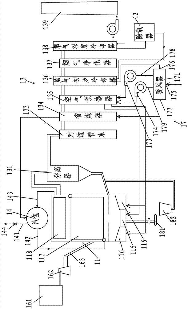
[0013] Such as figure 1 As shown, the combustion heating system using biomass as fuel in the present invention includes a combustion boiler 11, a flue gas discharge device 13, and an air supply device 17. The flue gas discharge device includes a cyclone separator 131, and the inlet of the cyclone separator 131 is connected to the combustion boiler 11, the flue gas outlet of the cyclone separator 131 is connected to the inlet of the convection tube bundle 133, and the solid matter outlet of the cyclone separator 131 communicates with the combustion zone of the combustion boiler 11 through its lower return pipe, and the combustion of the combustion boiler There are main and auxiliary combustion beds 115 and 116 in the area, and an economizer 134, a flue gas preliminary cooler 136, a flue gas purifier 137, and a flue gas deep cooler are arranged in sequence along the flue gas flow direction downstream of the convection tube bundle 133. 138 and anti-corrosion chimney 139, the flue...


PUM


Abstract

The invention relates to a combustion heat supply system taking biomass as a fuel. The combustion heat supply system comprises a combustion boiler, a flue gas emission device and an air supply device, wherein the flue gas emission device comprises a separator and a convection bank; the lower part of the convection bank is provided with a coal economizer, a flue gas primary cooler, a flue gas purifier, a flue gas deep cooler and a chimney; an inlet of a water flow pipeline positioned in the flue gas deep cooler is connected with a water source to be heated, and an outlet of the water flow pipeline passes through a deaerator and then is connected with water flow pipelines which are positioned in the flue gas primary cooler and the coal economizer; an outlet of the water flow pipeline positioned in the coal economizer is connected with a water inlet of a steam pocket; an water outlet of the steam pocket is connected with a water heating device positioned in the combustion boiler; a water heating device positioned in the combustion boiler is connected with a steam inlet of the steam pocket; a steam outlet pipe of the steam pocket is connected with a steam supply pipe. The combustion heat supply system taking the biomass as the fuel, which is disclosed by the invention, has the advantages of high heat supply efficiency and little environment pollution.

Description

technical field [0001] The invention relates to a heat supply device, in particular to a combustion heat supply device. Background technique [0002] Thermal energy is a major and essential way of energy consumption for residential heating, non-electric central air-conditioning and industrial production. In my country, heat supply methods include combined heat and power generation, regional boilers, decentralized boilers, electric heating film, heat pump technology, etc., mainly using coal as fuel, and using clean energy such as natural gas and electric energy in a small amount. Due to the low efficiency of these facilities, the high concentration of pollutant emissions, and the relatively close distance from the city, more and more environmental protection problems have been caused, especially the problem of urban air pollution. In the process of using biomass combustion to generate heat, zero emission of carbon dioxide can be achieved, clean and environmentally friendly, ...

Claims


Application Information

Patent Timeline
Patent Type & Authority Applications(China)
IPC IPC(8): F23C10/10F23C10/22F23C10/18F22B31/00F23J15/06F23L15/00F22D1/50
CPCY02E20/34
Inventor 宋振林李永华宋渝李曦
Owner 恩极而(上海)能源科技有限公司
Why Eureka
Try Eureka