Equipment and method for forming optical fiber bundle

A molding equipment and molding method technology, applied in the direction of coating, etc., can solve the problems of excessive twisting of optical fibers, different helix radii, and differences in the length of optical fiber ribbons, etc., and achieve the effects of tight bundled optical fibers, increased optical fiber density, and small mutual influence

Active Publication Date: 2014-02-19
GUANGDONG HENGTONG PHOTOELECTRIC SCI & TECH +1
View PDF3 Cites 7 Cited by
  • Summary
  • Abstract
  • Description
  • Claims
  • Application Information

AI Technical Summary

Problems solved by technology

Skeleton optical fiber ribbon cable production equipment requires a large investment, the most complicated process, and the highest production cost
The main structure of my country's optical fiber ribbon cable is that the optical fiber ribbon is helically twisted into the loose tube structure. This structure has an obvious problem, that is, due to the different helical radii of the optical fiber ribbons of different layers, the length of the central layer and the side layer of the optical fiber ribbon is different. In addition, there are disadvantages such as uneven excess length and excessive twisting of optical fiber.
At the same time, due to the helical twisting of the optical fiber ribbon, the optical fiber ribbon forms an almost fixed laminated body, making it difficult to make the remaining length larger. When subjected to short-term tension, the optical fiber is subject to a greater strain
In order to improve the tensile strength, the diameter of the reinforcement has to be increased, resulting in an increase in the diameter and hardness of the optical cable, which brings inconvenience to the construction, greatly increases the installation cost, and also consumes limited urban pipeline space
However, the optical fiber bundle manufacturing methods and molds in the prior art have low fiber density, high production cost and low production efficiency.

Method used


Image

  • Equipment and method for forming optical fiber bundle
  • Equipment and method for forming optical fiber bundle
  • Equipment and method for forming optical fiber bundle

Examples


Embodiment Construction

[0043] The preferred embodiments of the present invention will be described below in conjunction with the accompanying drawings. It should be understood that the preferred embodiments described here are only used to illustrate and explain the present invention, and are not intended to limit the present invention.

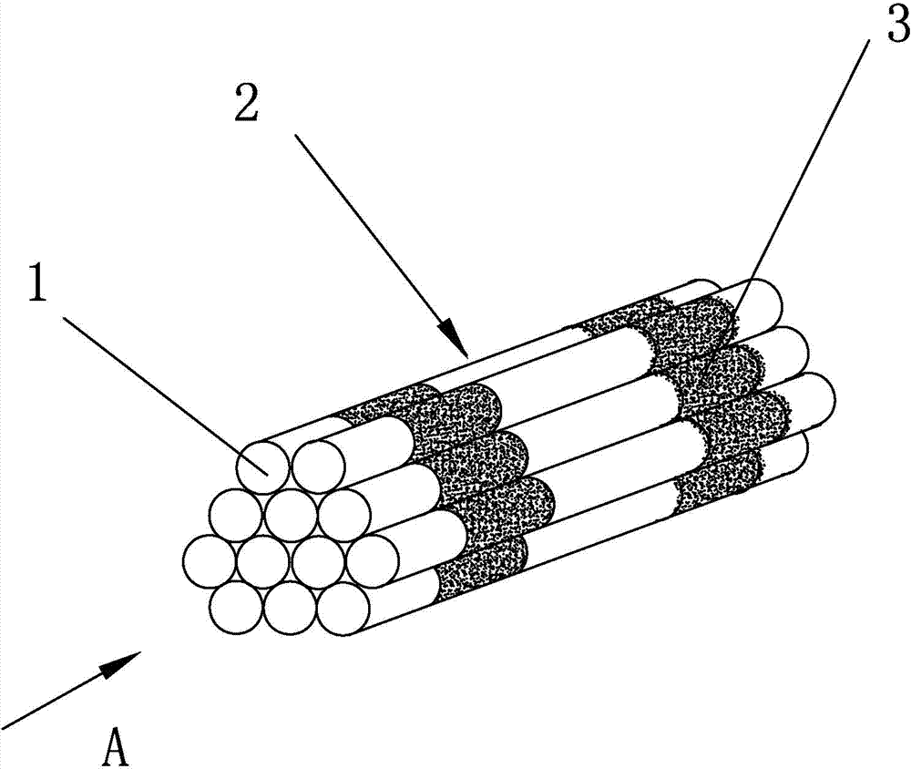
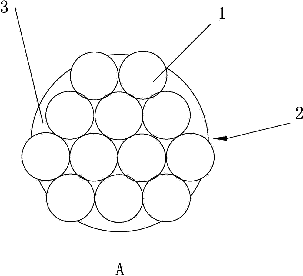
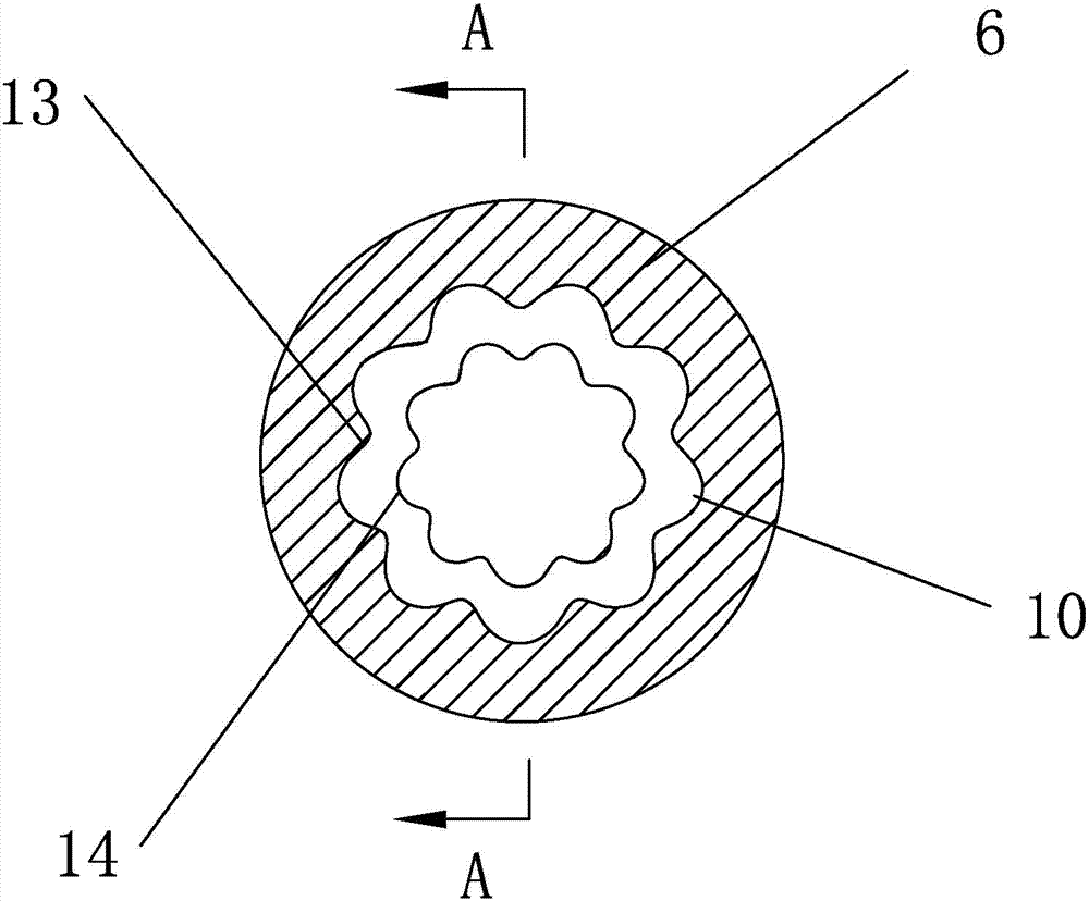
[0044] like Figure 3 to Figure 5 Shown, a kind of forming equipment of optical fiber bundle according to the present invention,

[0045]It sequentially includes a parallel tape pay-off machine 4 , a polymerization mold 5 , a preform mold 6 , an intermittent coating mold 7 , an ultraviolet light curing device 8 and a wire take-up device 9 . The preforming mold 6 has a forming cavity, the inner wall of the forming cavity is provided with a forming groove 10, the cross section of the forming cavity is formed by a plurality of arcs arranged in a circular array, one end of the forming cavity is set as the forming inlet 13, and the other end of the forming cavity is set ...


PUM

PropertyMeasurementUnit
lengthaaaaaaaaaa

Abstract

The invention discloses equipment for forming an optical fiber bundle. The equipment sequentially comprises a ribbon-combining pay-off machine, a polymerization mold, a pre-forming mold, an intermittent coating mold, an ultraviolet curing device and a take-up device, wherein the pre-forming mold is provided with a forming cavity; a forming groove is formed in the inner wall of the forming cavity; the cross section of the forming cavity is formed by distributing a plurality of arcs in an annular array; a forming inlet is formed in one end of the forming cavity; a forming outlet is formed in the other end of the forming cavity; the cross sections of the forming cavity from the forming inlet to the forming outlet are gradually reduced; the intermittent coating mold is of a tubular structure with a hollow inner cavity; a groove is formed in the inner wall of the intermittent coating mold. A central loose tube type optical cable or a stranded loose tube optical cable manufactured by the equipment has the advantages of small outer diameter of an optical cable, high optical fiber density and light weight; meanwhile, ultraviolet curable resin is intermittently coated at the periphery of bundle-shaped optical fibers, so that resin is saved, and the optical fibers have a certain degree of freedom, slightly influence one another, and are slightly stressed.

Description

technical field [0001] The invention belongs to the technical field of optical cable manufacturing, and in particular relates to an optical fiber bundle forming device and a forming method thereof. Background technique [0002] At present, with the development of fiber-to-the-home (FTTH) construction, the amount of information transmission and the demand for broadband services continue to grow, and the demand for large-core optical cables has increased significantly. The large-scale construction of metropolitan area network and access network makes the pipeline resources of urban optical cable layout more and more precious, and the large-core optical cable is limited by the space of urban underground pipelines. [0003] my country is laying a large number of feeder optical fiber ribbon cables in the metropolitan area network and access network. The optical cable structure has three types: central beam tube type, loose tube layer stranding type and skeleton type. Skeleton op...

Claims


Application Information

Patent Timeline
Patent Type & Authority Applications(China)
IPC IPC(8): B29C41/20B29C41/38B29C41/34
Inventor 许征刘婷
Owner GUANGDONG HENGTONG PHOTOELECTRIC SCI & TECH
Why Eureka
Try Eureka