Method and device for multi-head laser texturing processing of roller surface

A technology of laser texturing and rolling surface, applied in laser welding equipment, metal processing equipment, manufacturing tools, etc., can solve the problems of irregular textured point morphology, complicated control equipment, affecting the reflection effect of the board surface, etc., and achieve roughness. Good uniformity and deep drawing performance, improved wear resistance and service life, and high laser energy utilization efficiency

Inactive Publication Date: 2014-03-12
武汉钢铁有限公司
View PDF12 Cites 8 Cited by
  • Summary
  • Abstract
  • Description
  • Claims
  • Application Information

AI Technical Summary

Problems solved by technology

[0005] In order to solve the problem of orderly texturing of laser texturing equipment, the Chinese patent "A Laser Texturing Treatment Method for Roll Surface" (publication number: CN101642778A) proposes to speed up the movement rate of the laser texturing head along the axial direction of the roll and increase the helix inclination , but although the distribution of texturing pits is non-linear in the circumferential direction and length direction of the roll, it is orderly along the thread inclination direction. When the roll rolls the strip, it will also affect the surface of the plate at different angles. reflection effect
The Chinese patent "A Processing Method for Multi-Head Laser Disorder Texturing Roll Surface" (publication number CN102699524A) proposes to use a random signal generator to control the pulse laser, change the frequency and duty cycle of the laser pulse beam, and make the appearance of the texturing point Inconsistent with the distribution density to achieve disorder, the disadvantage is that it will have a certain impact on the roughness uniformity and deep drawing performance of the steel plate
In addition, the Chinese patent "Fiber Laser Texturing System" (publication number CN102380706A) makes the laser head rotate and deflect from side to side, which will also make the texturing point irregular in shape, and the control equipment is more complicated

Method used


Image

  • Method and device for multi-head laser texturing processing of roller surface
  • Method and device for multi-head laser texturing processing of roller surface
  • Method and device for multi-head laser texturing processing of roller surface

Examples


Embodiment 1

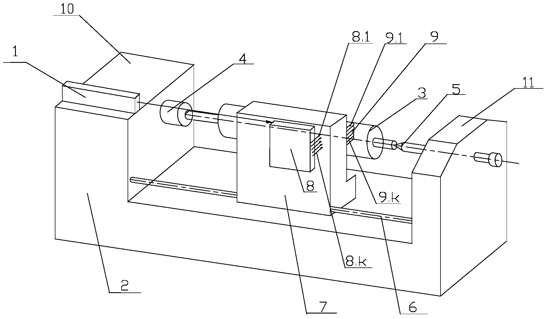
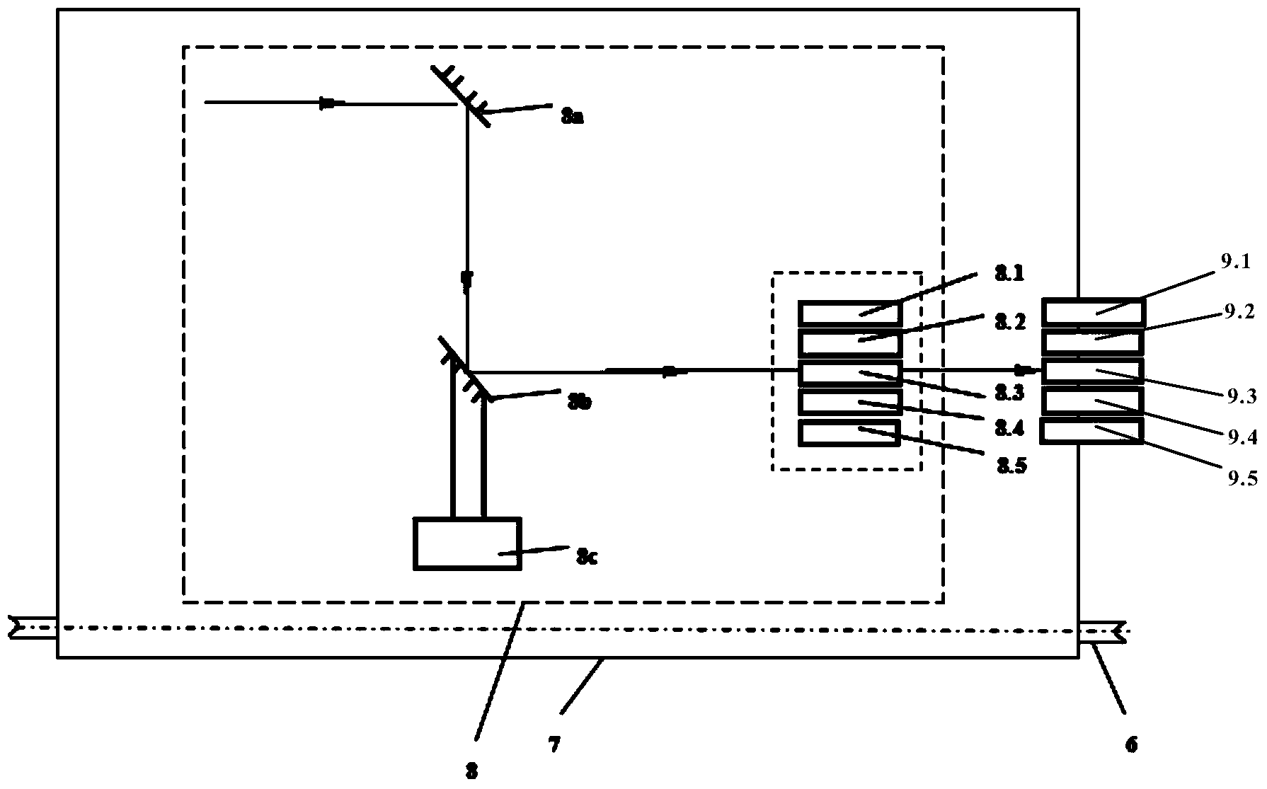
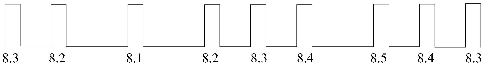
[0037] Such as figure 2 As shown, the vibration splitting mechanism 8 in Embodiment 1 has five parallel splitting heads, namely the first splitting head 8.1, the second splitting head 8.2, the third splitting head 8.3, the fourth splitting head 8.4 and the fifth splitting head 8.5 . Correspondingly, the laser focusing mechanism 9 in Embodiment 1 has five parallel focusing heads, that is, the first focusing head 9.1, the second focusing head 9.2, the third focusing head 9.3, the fourth focusing head 9.4 and the fifth focusing head. Focus head 9.5. The laser beam emitted by the laser 1 passes through the first total reflection mirror 8a, the optical path changes by 90°, and enters the second total reflection mirror 8b fixed to the vibrating device 8c, and the optical path changes by 90° again. When the second total reflection mirror 8b was at the amplitude zero point, the laser beam just entered the third beam splitting head 8.3 in the middle position, and when the second tot...

Embodiment 2

[0045] Embodiment 2 has the same basic structure as Embodiment 1, and the working principle is also the same. Only the number of beam-splitting heads of its vibrating beam-splitting mechanism 8 is slightly different from the number of focusing heads of the laser focusing head mechanism 9 .

[0046] Such as Figure 5 As shown, the vibration splitting mechanism 8 in Embodiment 2 has seven parallel splitting heads, i.e. the first splitting head 8.1, the second splitting head 8.2, the third splitting head 8.3, the fourth splitting head 8.4, the fifth splitting head 8.5 , the sixth split light head 8.6 and the seventh split light head 8.7. Correspondingly, the laser focus mechanism 9 in Embodiment 2 has seven parallel focus heads, that is, the first focus head 9.1, the second focus head 9.2, the third focus head 9.3, the fourth focus head 9.4 and the fifth focus head. Focusing head 9.5, sixth focusing head 9.6 and seventh focusing head 9.7.

[0047] In Example 2, the material of...


PUM


Abstract

The invention discloses a method and a device for the multi-head laser texturing processing of a roller surface. The method comprises the following steps: driving a to-be-processed roller to rotate on a numerically-controlled machine tool; driving a texturing platform, and a vibration light splitting mechanism and a laser focusing mechanism which are arranged on the texturing platform to axially translate along the to-be-processed roller in a reciprocating way; emitting continuous laser beams to the vibration light splitting mechanism by a laser, and driving the vibration light splitting mechanism to vibrate at a preset frequency so as to enable the laser beams to sequentially scan k parallel light splitting heads in the vibration light splitting mechanism; transmitting the laser beams which are received by the light splitting heads to the k parallel focusing heads of the laser focusing mechanism to carry out focusing, thereby forming the irregular spiral scanning curve lattice distribution of texturing pits on the surface of the to-be-processed roller. The device mainly comprises the laser, the numerically-controlled machine tool, a translation guide rail, the texturing platform, the vibration light splitting mechanism and the laser focusing mechanism, wherein the texturing platform is in sliding fit with the translation guide rail, and the vibration light splitting mechanism and the laser focusing mechanism are arranged on the texturing platform. Out-of-order uniform texturing can be realized on the surface of the roller, and the processing efficiency is high.

Description

technical field [0001] The invention relates to a roll surface roughening treatment technology, in particular to a roll surface multi-head laser texturing process method and a device thereof. Background technique [0002] The surface morphology of cold-rolled sheet steel has an important influence on the plate shape, deep drawability, elongation and coating performance, and the surface morphology of cold-rolled sheet steel depends to a large extent on the work roll during the cold-rolling production process. and the surface morphology of the leveling roll. Therefore, in the cold-rolled thin plate production process, it is required to roughen the roll surfaces of the cold-rolled work rolls and leveling rolls, and then roll out cold-rolled roughened steel plates that meet the special process requirements of users. [0003] So far, the development of roll texturing technology and equipment has gone through three stages: shot peening texturing, electric spark texturing and lase...

Claims


Application Information

Patent Timeline
IPC IPC(8): B23K26/36B23K26/08B23K26/064B23K26/70
CPCB23K26/0676B23K26/082B23K26/0823B23K26/3584
Inventor 蔡珍韩斌吴国胜汪水泽杨奕刘洋魏兵
Owner 武汉钢铁有限公司
Why Eureka
Try Eureka