Spinning technology of a spinning machine

A technology of spinning process and spinning machine, which is applied in the field of spinning process of spinning machine, and can solve the problems of broken viscose filaments, low filament strength, and insufficient reaction time of viscose filaments, etc.

Inactive Publication Date: 2014-03-19
YIBIN GRACE GROUP CO LTD +1
View PDF12 Cites 6 Cited by
  • Summary
  • Abstract
  • Description
  • Claims
  • Application Information

AI Technical Summary

Problems solved by technology

[0009] Disadvantages: low spinning speed, high post-processing costs, and increased production costs
[0012] Disadvantages: Since the silk sliver is washed and dried immediately, the strength of the sliver is low, the whiteness is low, the sliver is rough, and the quality is not as good as that of the semi-continuous spinning machine; in order to increase the sizing of the silk sliver, the sizing needs to be removed when the embroidery thread is dyed. Increase the production cost of downstream products; high quality requirements for raw materials (viscose)
[0021] 1. The above structure limits the length of the roller. The time for the viscose filament to walk on the roller is short, and the forming time of the viscose filament is short. If the spinning speed is to be increased, the reaction time of the viscose filament will inevitably be insufficient and the product quality will be reduced. , so the efficiency of the traditional semi-continuous spinning machine is reduced;
[0022] 2. In order to improve efficiency, multiple filaments are usually processed at the same time, but when multiple viscose filaments are wound on the existing spinning roller, they are easy to twist, causing the viscose filaments to break and affecting the viscose filaments. product quality;
[0024] 4. All the spinning rollers are fixed at one end, which will inevitably require an extremely complex transmission mechanism to drive...

Method used


Image

  • Spinning technology of a spinning machine
  • Spinning technology of a spinning machine
  • Spinning technology of a spinning machine

Examples


Embodiment 1

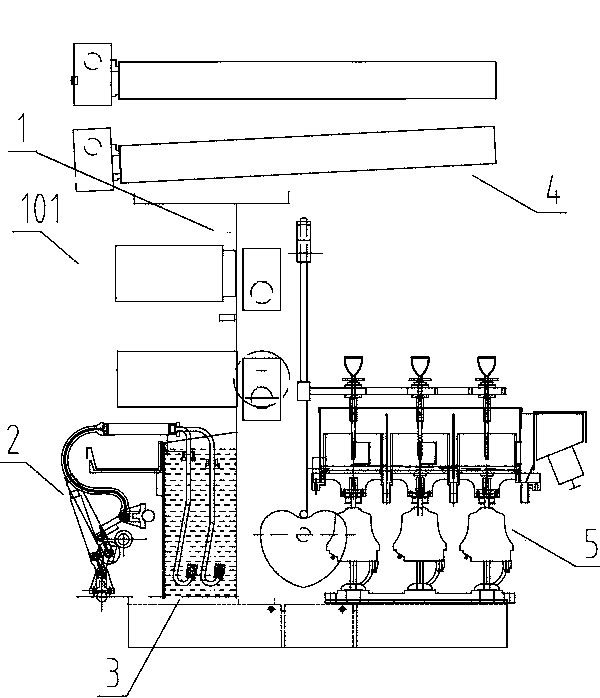
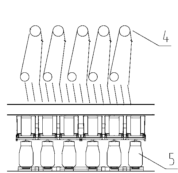
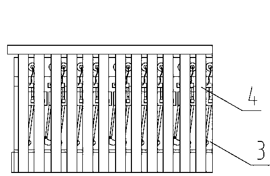
[0225] A spinning process of a spinning machine, comprising glue supply, filament forming, spinning and winding, the glue supply is completed by the glue supply device 2, and the filament forming is completed by the filament forming device 3, The spinning is completed by the spinning device 4, and the winding is completed by the winding device 5. The spinning device 4 includes a plurality of spinning rollers, and the two ends of the spinning rollers are fixed. The forming part of the winding device 5 is located on the outside of the area between the wallboards 6 on both sides of the frame 1, on the other side opposite to the spinning surface 101, and the spinning surface 101 refers to the outer side of the wallboard 6 outside the frame 1. 1. The area where the filament forming device 3 is provided, the other side opposite to the area is called the winding surface 7, and the winding device 5 includes a wet cake winding device 51, and / or a wet cylinder Packing winding device 52 ...

Embodiment 2

[0231]A spinning process of a spinning machine, comprising glue supply, filament forming, spinning and winding, the glue supply is completed by the glue supply device 2, and the filament forming is completed by the filament forming device 3, The spinning is completed by the spinning device 4, and the winding is completed by the winding device 5. The spinning device 4 includes a plurality of spinning rollers, and the two ends of the spinning rollers are fixed. The forming part of the winding device 5 is located on the outside of the area between the wallboards 6 on both sides of the frame 1, on the other side opposite to the spinning surface 101, and the spinning surface 101 refers to the outer side of the wallboard 6 outside the frame 1. 1. The area where the filament forming device 3 is provided, the other side opposite to the area is called the winding surface 7, and the winding device 5 includes a wet cake winding device 51, and / or a wet cylinder Packing winding device 52 a...

Embodiment 3

[0237] The spinning machine includes a frame 1, a glue supply device 2, a filament forming device 3, a spinning device 4 and a winding device 5, and the forming part of the winding device 5 is located between the wall panels 6 on both sides of the frame 1. The outer side of the area, the other side opposite to the spinning surface 101, the forming part of the winding device 5 includes the loose bobbin tube 5203 of the winding device 5 or a structure having the same function as the loose bobbin tube 5203; the spinning surface 101 Refers to the area on the outside of the frame 1 wallboard 6 that is provided with a filament forming device 3, and the other side opposite to the area is called the winding surface 7, and the spinning device 4 includes a plurality of spinning rollers, Both ends of the spinning roll are fixed, and the winding device 5 includes a wet cake winding device 51 . The frame 1 includes at least two uprights 1101 , and the wall panels 6 are installed on the upr...


PUM

PropertyMeasurementUnit
Inner diameter φaaaaaaaaaa
Lengthaaaaaaaaaa
Inner diameter φaaaaaaaaaa

Abstract

The invention relates to a spinning technology of a spinning machine. The spinning technology of the spinning machine comprises the steps of glue supply, silk forming, spinning and winding. The forming portion of each winding device used in the step of winding is located outside an area between two side wall plates of a machine frame and is located on the other side opposite to a spinning face. Each winding device comprises a wet disk-shaped winding device, and/or a wet cylindrical winding device and/or a wet twisted winding device. Wet silk obtained after the step of glue supply, the step of silk forming and the step of spinning is wound through the winding devices, so that wet cylindrical silk and/or wet twisted silk and/or wet disk-shaped silk are/is formed. The winding devices are arranged externally, so that the corrosion of the silk, the winding devices and a control system of the winding devices is small in an acid environment, maintenance is convenient, and manual operation is convenient. Due to the fact that an existing centrifugal cylinder needs high-speed rotation, energy consumption is large. The winding devices adopted by the spinning machine just needs to meet the requirement for the speed of spinning rollers, no other energy consumption is needed, and therefore the overall power of the spinning machine is low.

Description

technical field [0001] The invention relates to a spinning process, more specifically, the invention relates to a spinning process of a spinning machine, which belongs to the technical field of spinning. Background technique [0002] Pure methyl cellulose is extracted from cellulose raw material, called pulp. Treat with caustic soda and carbon disulfide to obtain orange-yellow cellulose xanthate sodium, and then dissolve it in dilute sodium hydroxide solution to become viscous spinning stock solution, called viscose. After the viscose is filtered, matured and defoamed, it is wet-spun, and the coagulation bath is composed of sulfuric acid, sodium sulfate and zinc sulfate. Sodium cellulose xanthate in the viscose reacts with sulfuric acid in the coagulation bath to decompose, and the cellulose is regenerated and precipitated. The obtained cellulose fiber becomes viscose fiber after washing, desulfurization, bleaching and drying. Viscose filament is a kind of viscose fiber, w...

Claims


Application Information

Patent Timeline
IPC IPC(8): D01D5/06D01F2/06
Inventor 冯涛廖周荣孙毅段太刚何大雄徐发祥刘志军汤伟曹阳
Owner YIBIN GRACE GROUP CO LTD
Why Eureka
Try Eureka