Subwavelength plasmon polarization converter
A polarization converter and plasmon technology, applied in instruments, electrical components, optical components, etc., can solve the problems of low efficiency of polarization converters, complicated preparation, narrow bandwidth, etc., and achieve large working bandwidth, high conversion efficiency, simple structure
- Summary
- Abstract
- Description
- Claims
- Application Information
AI Technical Summary
Problems solved by technology
Method used
Image
Examples
Embodiment 1
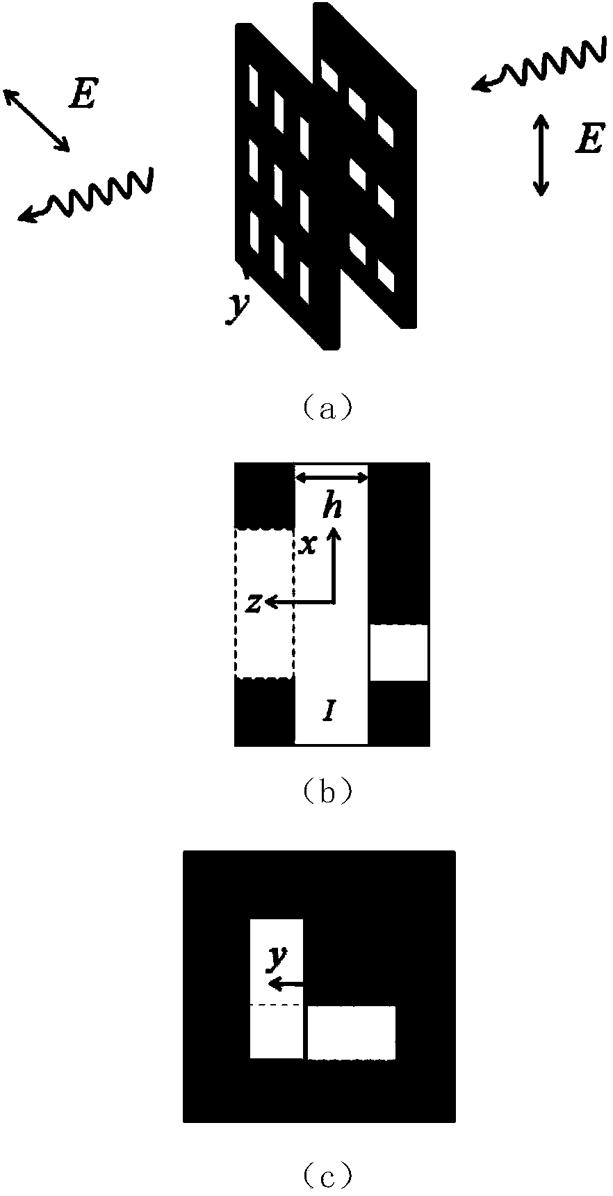
[0023] As a first embodiment, the working frequency of the polarization converter is in the optical frequency band. The converter is composed of a gold film / silicon nitride / gold film sandwich structure, and pre-designed microstructures are respectively prepared on the gold film. During the experiment, a 100-nm-thick gold film was coated on both sides of a suspended 50-nm-thick silicon nitride film by magnetron sputtering, and then a focused ion beam (FIB) system was used to coat the gold films on both sides. Subwavelength pinhole arrays were fabricated separately. The period of the prepared small hole array is 600 nanometers, the length of the rectangular small holes is 400 nanometers, and the width is 150 nanometers, and the size of the entire array is 50 micrometers*50 micrometers. In order to align the rectangular holes on both sides into an L-shaped "cross", four through-marks were made with FIB at the four corners of the sample during processing to assist in positioning ...
Embodiment 2
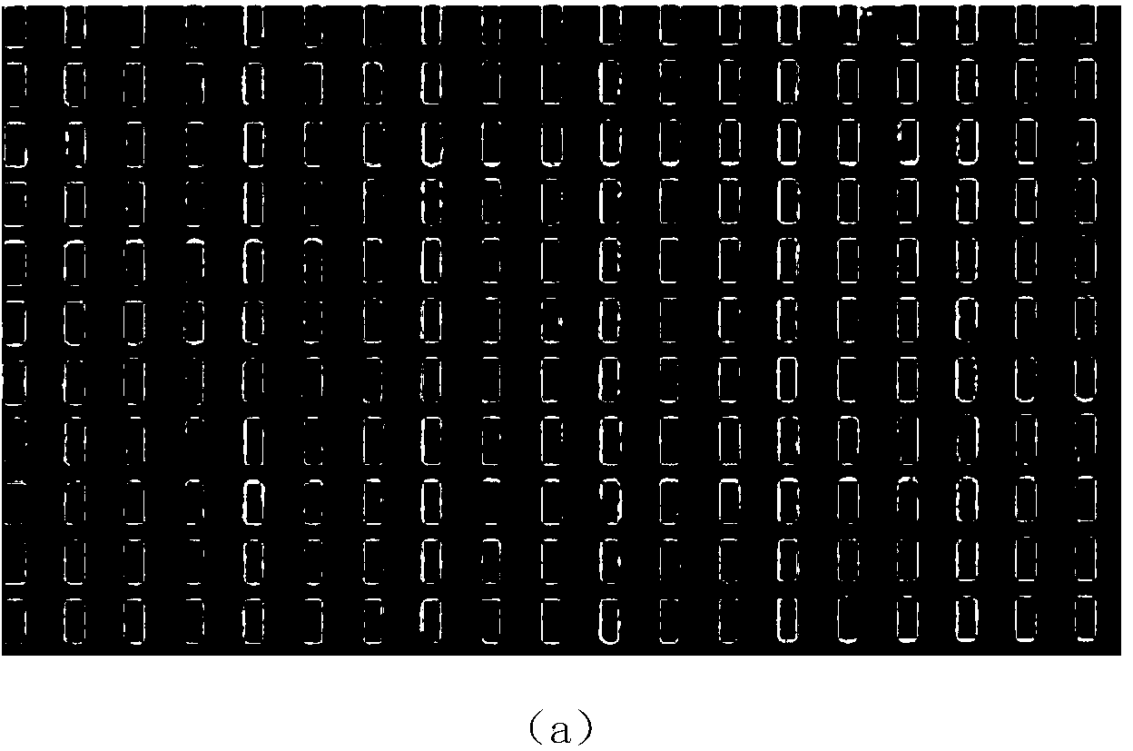
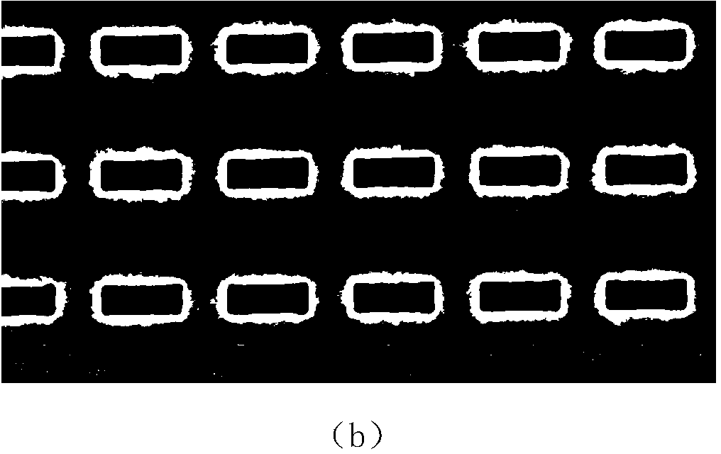
[0028] As a second embodiment, the working frequency of the polarization converter is in the microwave range. Figure 6 (a) and Figure 6 (b) Actual pictures of a single polarizer and a polarization converter processed by water cutting (water jet), respectively. The perforated metal plate is made of aluminum, its thickness is t=1.5 mm, the period of the hole array is d=60 mm, the side length of the rectangular hole is l=40 mm, and the width w=10 mm. The side length of the entire sample is 660 mm, and contains 11*11 rectangular holes in total. The two metal plates of the converter are separated by an air layer, and the small holes form an L-shaped vertical "cross", and the distance between the plates can be adjusted freely. Figure 6 (c) The experimentally measured transmission spectra (circles and squares) of a single polarizer are given. Two transmission peaks were detected in the incident polarization x direction (T xx , square): The main peak is at 3.53GHz, and the seco...
Embodiment 3
[0031] Based on the above results, the present invention further proposes a design method of a "universal" polarization converter. The converter can switch the polarization of the incoming line to any polarization direction, including orthogonal directions prohibited by Malius' law. To achieve this goal, two schemes are proposed here. The first scheme acts as a transition scheme, which uses Figure 6 The polarizer in (a) acts as the input polarizer, while the output polarization direction is controlled by different output polarizers. The output polarizer is still made of metal aluminum plate, engraved with periodic oblique rectangular holes (the angle θ between the long side of the rectangular hole and the horizontal direction can be set according to needs; the corresponding rectangular holes of the incident and outgoing polarizers form ∠-shaped "cross"). as an example, Figure 8 (a) Gives a real picture of the exit polarizer at θ = 30 degrees. Figure 8 (b) shows the exp...
PUM
 Abstract
Description
Claims
Application Information
 - R&D
- Intellectual Property
- Life Sciences
- Materials
- Tech Scout
- Unparalleled Data Quality
- Higher Quality Content
- 60% Fewer Hallucinations
Browse by: Latest US Patents, China's latest patents, Technical Efficacy Thesaurus, Application Domain, Technology Topic, Popular Technical Reports.
© 2025 PatSnap. All rights reserved.Legal|Privacy policy|Modern Slavery Act Transparency Statement|Sitemap|About US| Contact US: help@patsnap.com


