Frequency conversion shaker transmission case

A transmission box and box body technology is applied in the field of shaker transmission boxes to achieve the effects of reducing noise, reducing wear and tear of parts and lowering production costs

Inactive Publication Date: 2015-06-17
王用铭
View PDF6 Cites 0 Cited by
  • Summary
  • Abstract
  • Description
  • Claims
  • Application Information

AI Technical Summary

Problems solved by technology

[0006] The purpose of the present invention is to provide a frequency shaker transmission box that effectively solves various defects of the 6-s shaker transmission box

Method used


Image

  • Frequency conversion shaker transmission case
  • Frequency conversion shaker transmission case
  • Frequency conversion shaker transmission case

Examples


Embodiment 1

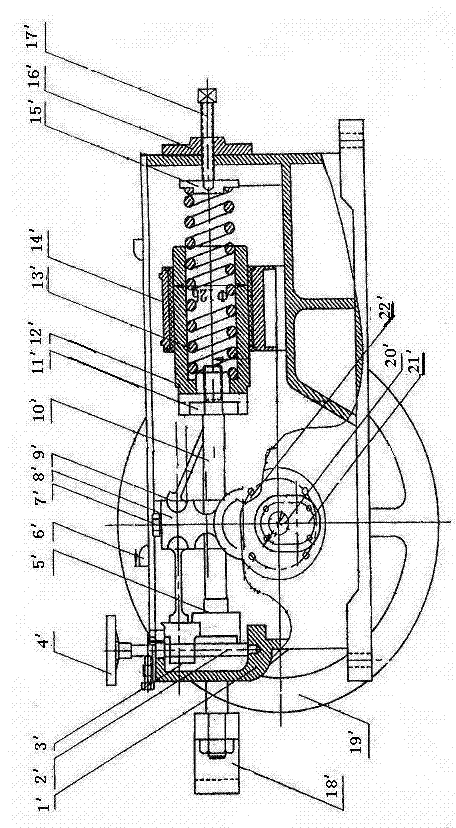
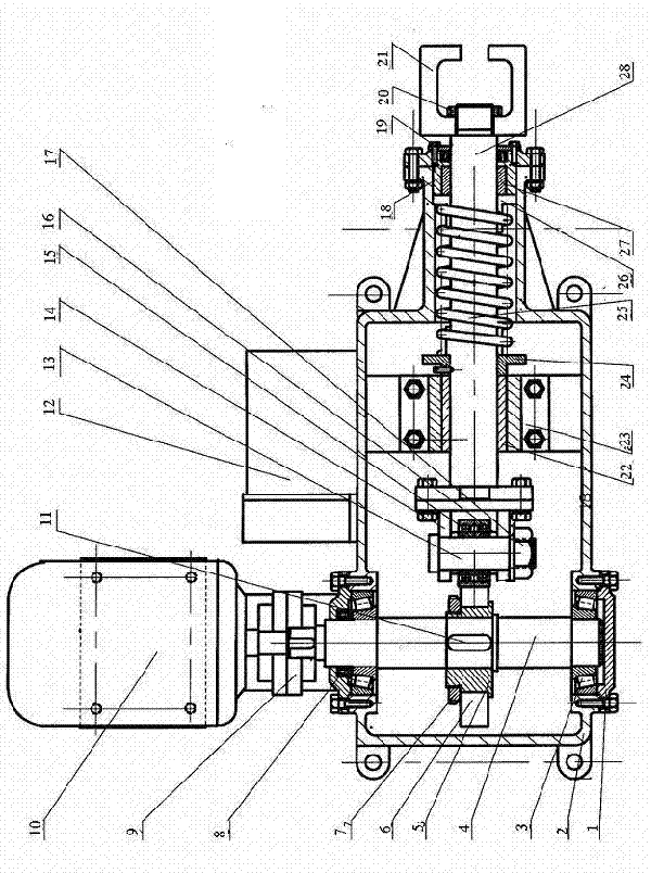
[0028] figure 2 , 3 As shown, the transmission principle of YM-variable frequency shaker transmission box: the eccentric main shaft 4 is directly connected with the motor 10 through the coupling 9, the eccentric main shaft 4 and the eccentric inner sleeve 5 are fixed together, the eccentric cam 6 is set on the eccentric inner sleeve 5, The required stroke can be adjusted by rotating the relative position of the eccentric cam 6 and the eccentric inner sleeve 5. The eccentric cam 6 and the eccentric inner sleeve 5 are marked with corresponding stroke marks. Tighten it so that the eccentric cam 6, the eccentric inner sleeve 5, and the eccentric main shaft 4 are fixed together and rotate at the same time. Since the eccentric cam 4 is always in contact with the rolling bearing 15 on the end face of the reciprocating main shaft 28, with the rotation of the eccentric cam 6, it turns from the lowest point to the highest point, the rolling bearing 15 and the reciprocating main shaft ...

Embodiment 2

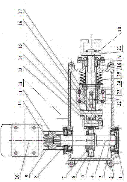
[0031] image 3 , 5 As shown, the spring 25 in the transmission box of the YM-variable frequency shaking table is changed to a butterfly spring, and corresponding improvements are made to the shape of the box and the matching spring support plate 26, positioning copper sleeve 27, and reciprocating main shaft 28 to make the frequency conversion shaking table drive Box, the structure is more compact.

[0032] The start and operation of the YM-variable frequency shaker motor is controlled by a frequency converter, and its motor start is soft start. At present, the way to start the motor is basically a hard start, that is, the power supply directly supplies power to the motor through the switch. Since the motor is in a power failure state, in order To overcome the inertia of the motor rotor, the current in the winding is very large. Under the action of the large current, the motor speed rises rapidly and reaches the rated speed in a short time. At this time, the speed cannot ...


PUM


Abstract

The invention provides a frequency conversion shaker transmission case, and relates to a vibration transmission machine, in particular to the shaker transmission case. The shaker transmission case effectively overcomes the various defects of a 6-s shaker transmission case, enables the stroke of the transmission case to be capable of being adjusted within 0-30 millimeters, and greatly improves the recovery rate of valuable minerals. The shaker transmission case comprises a motor, a case body, a coupler, an eccentric main shaft, an eccentric cam, a reciprocating main shaft, a reciprocating main shaft base, a spring base, a spring, a spring supporting plate and a linkage base, wherein the eccentric main shaft is arranged on the case body, and the direction of the eccentric main shaft is vertical to that of the reciprocating main shaft. The shaker transmission case is characterized by further comprising a frequency converter, and the frequency converter controls current input of the motor. A shaker is controlled by the frequency conversion technology, so the transmission case is low in vibration, stable in operation, low in noise, long in service life and capable of saving 15-20% of electricity, and electric energy consumption is greatly reduced.

Description

technical field [0001] The invention relates to a vibration transmission machine, in particular to a shaking table transmission box. Background technique [0002] Ore dressing with shaking table equipment is one of the main equipments for gravity beneficiation today. It is widely used in the separation of tungsten, tin, tantalum, niobium and other rare metals and precious metal ores. When dealing with heavy metal ores such as tungsten and tin, the 6-s shaking table is mainly used at present. The effective recovery of ore particle size is restricted by the stroke of the shaking table. The effective stroke of the 6-s shaking table is 8-32 mm. The particle size of beneficiation recovery can only be limited in the range of 2-0.05 mm, and the fine ore particles smaller than 0.05 mm cannot be recovered and will be discarded in the tailings, resulting in the loss of resources. [0003] 6-s shaking table transmission box, it produces reciprocating motion on the bed surface of th...

Claims


Application Information

Patent Timeline
Patent Type & Authority Patents(China)
IPC IPC(8): B03B5/06F16H25/08
Inventor 王用铭
Owner 王用铭
Why Eureka
Try Eureka