Liquid crystal display and manufacturing method thereof

A liquid crystal display and liquid crystal technology, applied in the direction of instruments, nonlinear optics, optics, etc., can solve problems such as high cost of glass substrates, lack of strokes on display, hidden dangers of electrical corrosion, etc., to prevent electrical corrosion, improve display uniformity, and improve The effect of the overall stability

Inactive Publication Date: 2014-03-26
江苏骏成电子科技股份有限公司
View PDF0 Cites 0 Cited by
  • Summary
  • Abstract
  • Description
  • Claims
  • Application Information

AI Technical Summary

Problems solved by technology

In addition to affecting the uniformity of display contrast, the large resistance will also affect the stability of IC signal transmission on the glass, and it is very likely that garbled characters and error messages will be displayed on the liquid crystal display
In other words, the above missing will seriously affect the stability and reliability of COG product display
Furthermore, according to the existing technology, it is difficult to directly reduce the wiring width of the ITO to overcome the above-mentioned defects.
[0005] In order to solve the above-mentioned deficiency, a new type of indium tin oxide glass substrate is provided in the prior art, which has the characteristics of a low square resistance value of about 5Ω / sq; but the cost of the new type of glass substrate is much higher than that of traditional glass Substrate 80Ω / sq cost
[0006] In addition, there is another deficiency in the liquid crystal display with ITO as the wiring electrode, that is, the hidden danger of electric corrosion
Due to the various and complex processes of liquid crystal displays, it is easy to leave cleaning liquid on the wiring electrodes of ITO and cause contamination by human hands.
During the long-term operation of the liquid crystal display, the problem of residual cleaning liquid and pollution will make the ITO electrodes with fine lines prone to electrolytic corrosion, resulting in lack of strokes on the display, which seriously affects the service life of the liquid crystal display

Method used


Image

  • Liquid crystal display and manufacturing method thereof
  • Liquid crystal display and manufacturing method thereof
  • Liquid crystal display and manufacturing method thereof

Examples


Embodiment 1

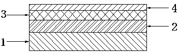
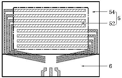
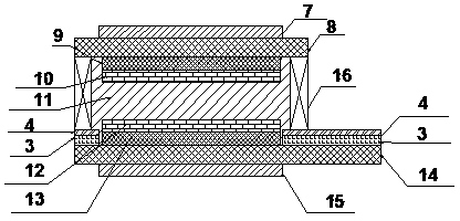
[0039] Embodiment 1: as Figure 1-3 The liquid crystal display shown comprises the liquid crystal box viewing area 5, the terminal lead area 6 and the metal layer outside the liquid crystal box. The viewing area 54 in the liquid crystal cell; the viewing area 5 of the liquid crystal cell is a composite layer structure, which successively includes a front polarizer 7, a front transparent glass substrate 8, a front insulating layer 9, a front vertical alignment layer, a liquid crystal layer 11, and a rear vertical alignment layer , a rear insulating layer 13, a rear transparent glass substrate 14 and a rear polarizer 15, the liquid crystal layer 11 is surrounded by a frame glue 16; one end of the rear transparent glass substrate 14 is flush with the front transparent glass substrate 8, and the other end is longer than the front transparent glass substrate 8 Transparent glass substrate 8, the outer terminal lead area 6 of the liquid crystal cell is the part where the rear transpa...

Embodiment 2

[0050] Embodiment 2: as Figure 4 Shown, substantially the same as embodiment 1, difference is: make nickel-plated layer 3 and gold-plated layer 4 in liquid crystal box internal viewing area 54, adopt the thickness of nickel-plated layer 3 to be 2.0 micron, adopt the thickness of gold-plated layer 4 to be 0.15 microns, the square resistance value of the glass substrate is reduced to 0.2 Ω / sq, and then the parallel alignment layers 10' and 12' are selected, and the thickness of the liquid crystal layer 11 is set to 6 microns, and the Δn is 0.145 positive liquid crystals, and the diameter of 6 microns is selected For plastic balls, set the twist angle formed by front and rear friction to 240°, and select SMD-570TA and QPF-205TF2 at the same time.

Embodiment 3

[0051] Embodiment 3: as Figure 5 As shown, it is basically the same as in Embodiment 1, and the difference is that a nickel-plated layer 3 and a gold-plated layer 4 are made in the terminal lead area 6 outside the liquid crystal cell, and the thickness of the nickel-plated layer 3 is 2.0 microns, and the thickness of the gold-plated layer 4 is adopted. 0.15 microns, the square resistance value of the glass substrate is reduced to 0.3 Ω / sq, select parallel alignment layers 10', 12', set the liquid crystal layer 11 to be a positive liquid crystal with a thickness of 7 microns and Δn of 0.15, and select a 7 micron diameter For plastic balls, set the twist angle formed by front and rear friction to 90°, and select QPF-215T and QPF-215T at the same time.


PUM

PropertyMeasurementUnit
diameteraaaaaaaaaa
thicknessaaaaaaaaaa
thicknessaaaaaaaaaa

Abstract

The invention discloses a liquid crystal display. The liquid crystal display comprises a liquid crystal box visual area, a liquid crystal box external terminal lead area and metal layers. The liquid crystal box visual area is divided into a liquid crystal box main visual area and liquid crystal box inner visual areas located all around the liquid crystal box main visual area. The liquid crystal box visual area sequentially comprises a front Polaroid, a front transparent glass substrate, a front insulating layer, a front directional layer, a liquid crystal layer, a rear directional layer, a rear insulating layer, a rear transparent glass substrate and a rear Polaroid from front to back, and frame adhesives are arranged all around the liquid crystal layer. One end of the rear transparent glass substrate is flush with the front transparent glass substrate, the other end of the rear transparent glass substrate is longer than the front transparent glass substrate, the liquid crystal box external terminal lead area is the part by which the rear transparent glass substrate is longer than the front transparent glass substrate, the metal layers are arranged on the rear transparent glass substrate and located outside the liquid crystal main visual area, the metal layers comprise the first metal layer and the second metal layer and the first metal layer, the second metal layer and the rear transparent glass substrate are sequentially connected from outside to inside. The liquid crystal display is high in contrast ratio, good in displaying evenness and capable of preventing electro-corrosion.

Description

technical field [0001] The invention relates to the technical field of liquid crystal displays, in particular to a liquid crystal display. Background technique [0002] Currently, liquid crystal displays generally use indium tin oxide (ITO) as a conductive material for wiring electrodes. [0003] However, due to the large square resistance value of ITO, it is difficult to make it small. The square resistance value must be at least greater than 5Ω / sq. Each pixel in the display shows uneven contrast. [0004] In addition, high-channel dot-matrix liquid crystal display (COG) products have fine and dense wiring, and the general wiring width and spacing are below 20 microns. Due to the ITO wiring, the square resistance value reaches more than several thousand ohms. In addition to affecting the uniformity of display contrast, the large resistance will also affect the stability of IC signal transmission on the glass, and it is very likely that garbled characters and error message...

Claims


Application Information

Patent Timeline
Patent Type & Authority Applications(China)
IPC IPC(8): G02F1/13G02F1/1333
Inventor 应发祥郭汉泉
Owner 江苏骏成电子科技股份有限公司
Why Eureka
Try Eureka