Organic light-emitting device and preparation method thereof
An electroluminescent device and electroluminescent technology, which are applied in the fields of electro-solid devices, semiconductor/solid-state device manufacturing, electrical components, etc., can solve the problems of total reflection loss, low light output performance, refractive index difference, etc., and achieve enhanced scattering ability, The effect of large specific surface area and improved light extraction efficiency
- Summary
- Abstract
- Description
- Claims
- Application Information
AI Technical Summary
Problems solved by technology
Method used
Image

Examples
preparation example Construction
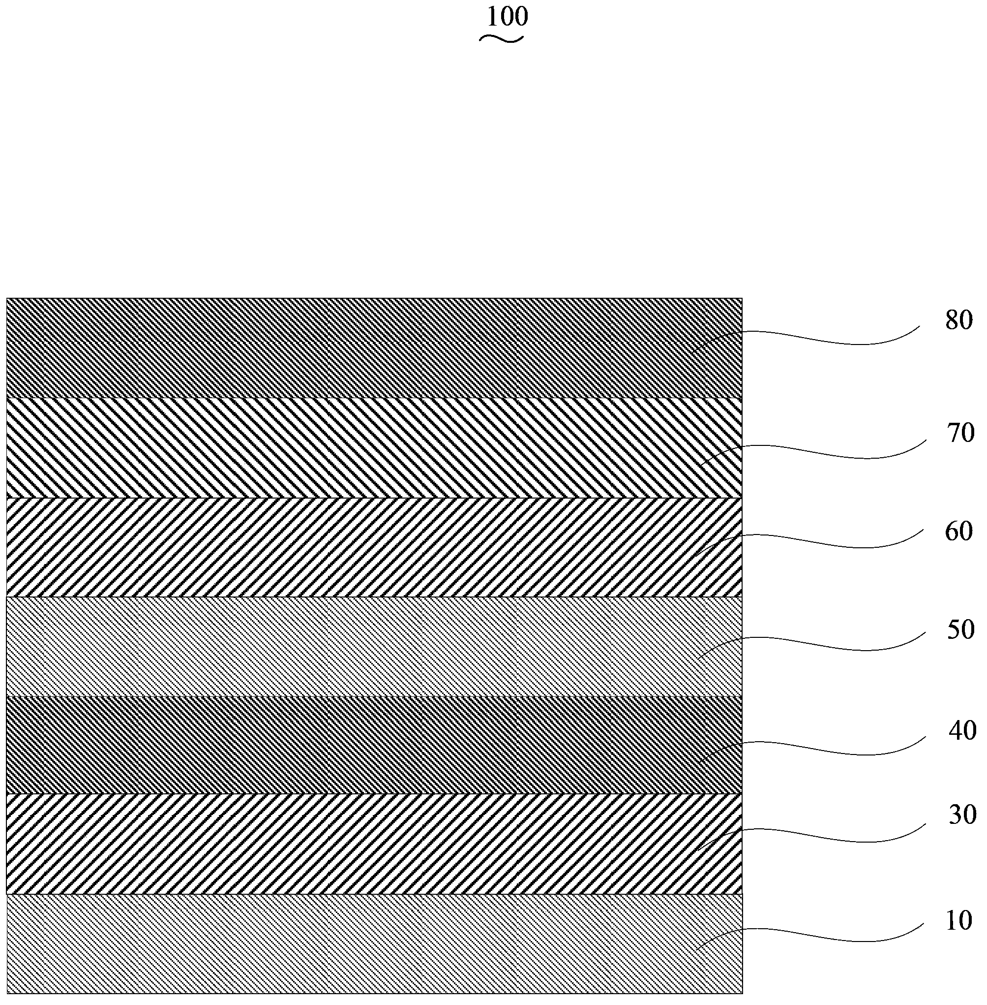
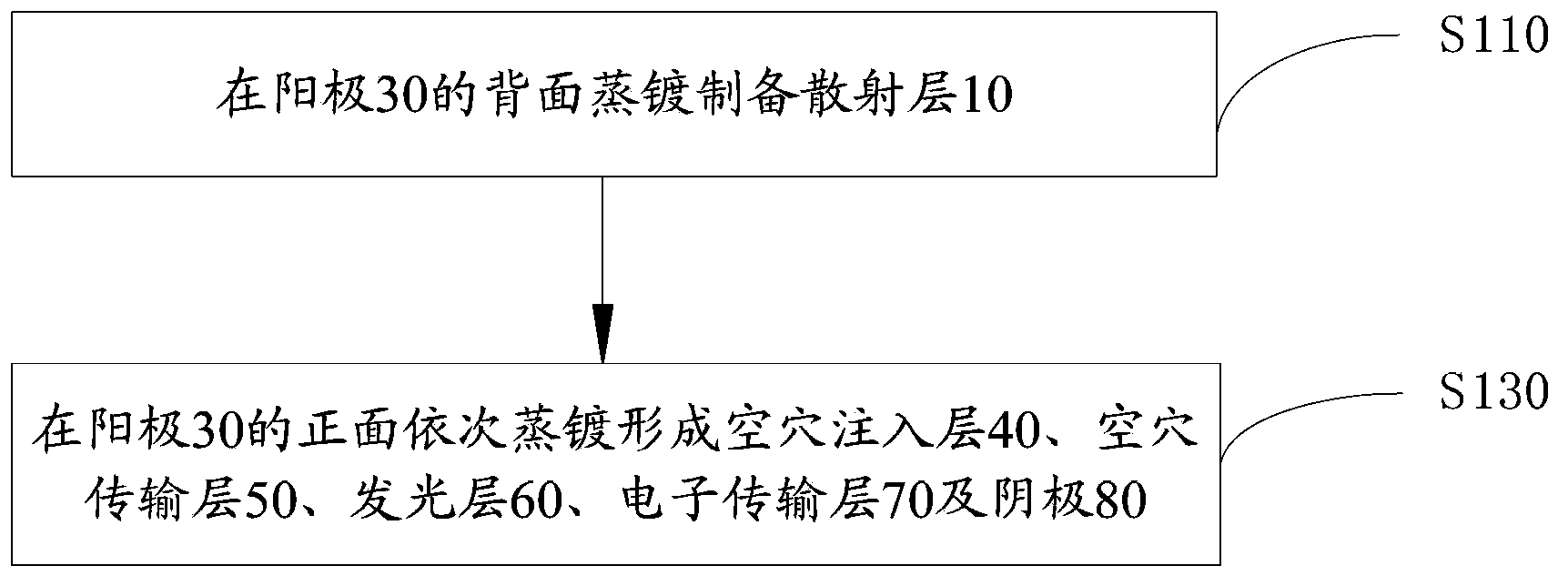
[0032] Please also see figure 2 , the preparation method of the organic electroluminescent device 100 of an embodiment, it comprises the following steps:
[0033] Step S110 , preparing the scattering layer 10 by evaporation on the back of the anode 30 .
[0034] The anode 30 is indium tin oxide glass (ITO), aluminum zinc oxide glass (AZO) or indium zinc oxide glass (IZO), preferably ITO. A conductive layer is formed on one side of the anode 30 , the side on which the conductive layer is formed is the front side, and the side on which the conductive layer is not formed is the back side.
[0035] In this embodiment, the anode 30 is pretreated before the scattering layer 10 is vapor-deposited on the back surface of the anode 30 . The pretreatment of the anode 30 is as follows: the anode 30 is first subjected to photolithography treatment, cut into the required size, and then ultrasonically cleaned with detergent, deionized water, acetone, ethanol, and isopropanone for 15 minut...
Embodiment 1
[0050] The structure prepared in this example is TiO 2 :ZnO / ITO glass / V 2 o 5 / TCTA / DCJTB / Bphen / Al organic electroluminescent devices.
[0051] First use detergent, deionized water, and ultrasonic for 15 minutes to remove the organic pollutants on the glass surface, and then prepare a scattering layer on the back of the conductive anode substrate (the side without the conductive layer). The scattering layer is TiO 2 : ZnO, the particle diameter of titanium dioxide is 100nm, the particle diameter of zinc oxide is 50nm, takes by weighing zinc oxide 3.5g, titanium dioxide 35g, adds 100g n-butanol, stirs and mixes to obtain suspension, and adds dispersant acetylacetone 10ml, emulsifier Triton 2ml, glass rod scraping method back and forth multiple times scrape coating, after scraping directly calcined at 450 ° C for 30 minutes to obtain a scattering layer with a thickness of 15 μm, and then on the front side of the conductive anode substrate (the side with the conductive layer) ...
Embodiment 2
[0056] The structure prepared in this example is TiO 2 :ZnO / AZO glass / MoO 3 / TAPC / Alq 3 / TPBi / Au organic electroluminescent devices.
[0057] First use detergent, deionized water, and ultrasonic for 15 minutes to remove the organic pollutants on the glass surface, and then prepare a scattering layer on the back of the conductive anode substrate (the side without the conductive layer). The scattering layer is TiO 2 : ZnO, the particle diameter of titanium dioxide is 200nm, and the particle diameter of zinc oxide is 20nm, takes by weighing zinc oxide 2.25g, titanium dioxide 15g, adds 100g water, stirs and mixes and obtains suspension, and adds dispersant acetylacetone 2ml, emulsifying agent song La Through 5ml, the glass rod scraping method is used to scrape back and forth multiple times. After scraping, it is directly calcined at 500 ° C for 20 minutes to obtain a scattering layer with a thickness of 30 μm, and then vapor-deposited on the front side of the conductive anode su...
PUM
| Property | Measurement | Unit |
|---|---|---|
| thickness | aaaaa | aaaaa |
| particle diameter | aaaaa | aaaaa |
| particle diameter | aaaaa | aaaaa |
Abstract
Description
Claims
Application Information
 - R&D
- Intellectual Property
- Life Sciences
- Materials
- Tech Scout
- Unparalleled Data Quality
- Higher Quality Content
- 60% Fewer Hallucinations
Browse by: Latest US Patents, China's latest patents, Technical Efficacy Thesaurus, Application Domain, Technology Topic, Popular Technical Reports.
© 2025 PatSnap. All rights reserved.Legal|Privacy policy|Modern Slavery Act Transparency Statement|Sitemap|About US| Contact US: help@patsnap.com