

Organic light-emitting device and preparation method thereof
An electroluminescent device and electroluminescent technology, which are applied in the fields of electro-solid devices, semiconductor/solid-state device manufacturing, electrical components, etc., can solve the problems of refractive index difference, total reflection loss, low light output performance, etc., and achieve enhanced scattering ability, Prevent aging and enhance the effect of luminous efficiency
- Summary
- Abstract
- Description
- Claims
- Application Information
AI Technical Summary
Problems solved by technology
Method used
Image

Examples
preparation example Construction
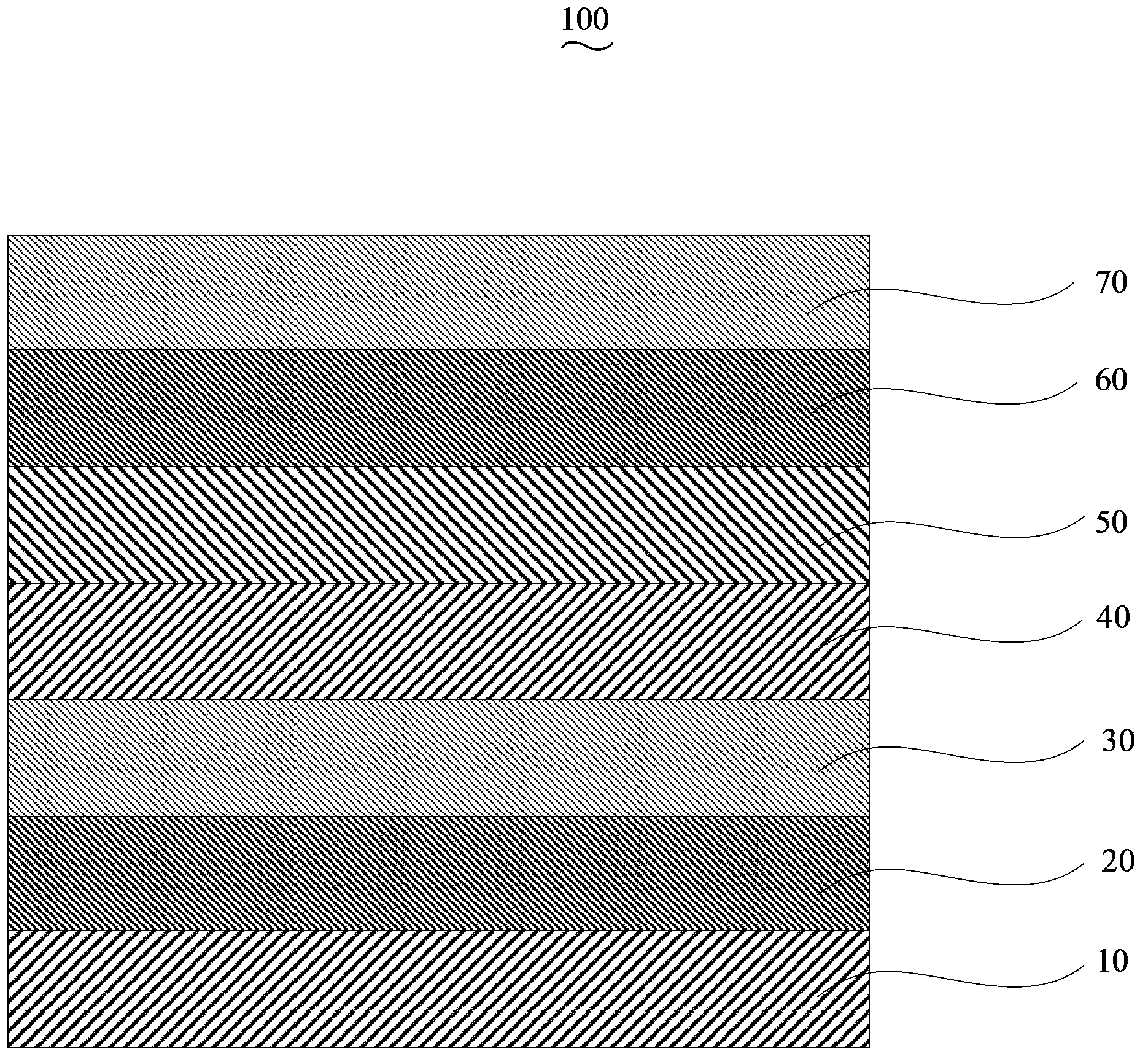
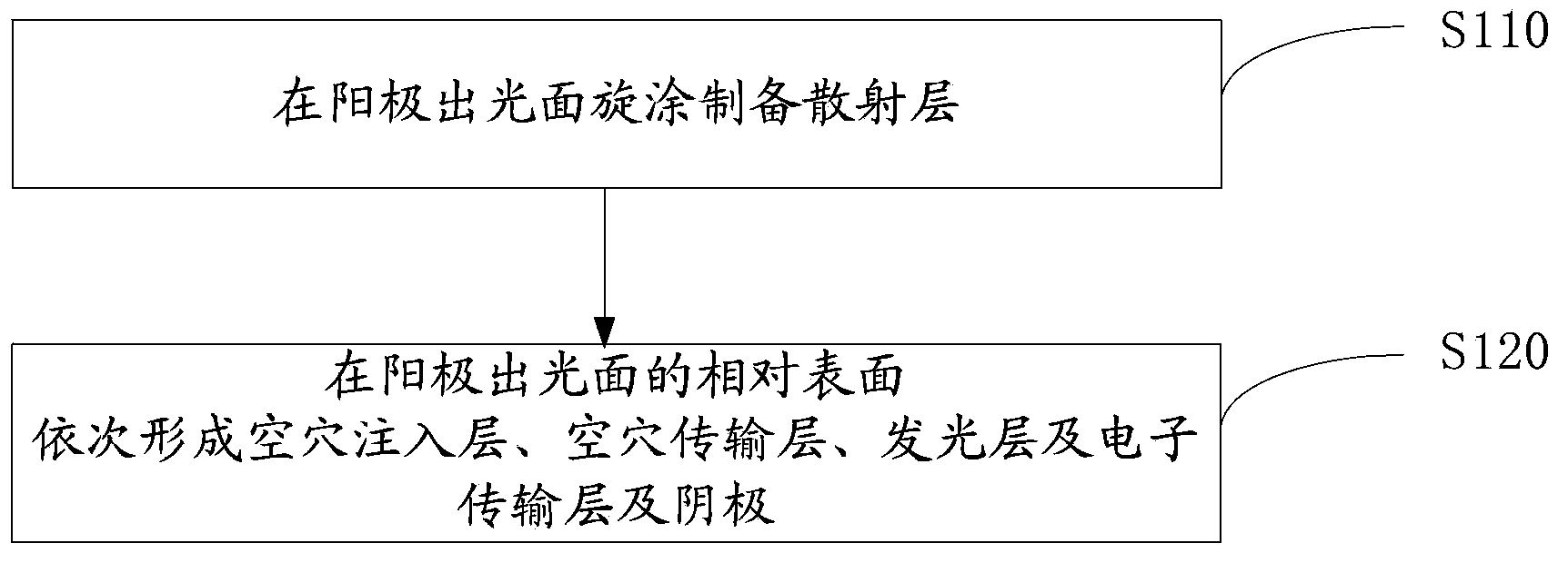
[0033] Please also see figure 2 , the preparation method of the organic electroluminescent device 100 of an embodiment, it comprises the following steps:
[0034] Step S110 , preparing the scattering layer 10 by spin-coating on the light-emitting surface of the anode 20 .
[0035] The material of the scattering layer 10 includes a host material and calcium oxide doped in the host material. The host material is selected from poly 3-hexylthiophene (P3HT), poly 3,4-dioxyethylthiophene (PEDOT), poly 3-formaldehyde At least one of polydodecylthiophene (P3AT) or polydodecylthiophene (P3DDT); the thickness of the scattering layer is 50nm~300nm; the mass percentage of calcium oxide in the scattering layer in the host material is 1%~30 %; the spin coating method specifically includes the following steps, first dissolving the host material and calcium oxide in an organic solvent to obtain a mixture, the total mass of the host material and the calcium oxide accounting for the mass perc...
Embodiment 1
[0050] The structure prepared in this example is P3HT:CaO / ITO / MoO 3 / TCTA / BCzVBi / Bphen / Al organic electroluminescent devices.
[0051] First, carry out photolithography treatment on ITO, cut it into the required size, and then use detergent, deionized water, acetone, ethanol, and isopropanol to sonicate for 15 minutes each to remove organic pollutants on the glass surface; clean the conductive substrate Appropriate treatment: oxygen plasma treatment, the treatment time is 5min, the power is 30W; the scattering layer is spin-coated on the light-emitting surface of the conductive anode, and the material is P3HT:CaO, wherein the mass percentage of CaO to the total mass of P3HT and CaO is 20%. P3HT and CaO were dissolved in the organic solvent chlorobenzene to obtain a mixture, the total mass of P3HT and CaO accounted for 20% of the mass percent of chlorobenzene, and the mixture was coated on the light-emitting surface of the anode by spin coating. The spin-coating speed is 4000r...
Embodiment 2
[0056] The structure prepared in this example is P3DDT:CaO / IZO / WO 3 / TAPC / Alq 3 / TPBi / Au organic electroluminescent devices.
[0057] First, use detergent, deionized water, and ultrasonic for 15 minutes to remove the organic pollutants on the glass surface. After cleaning, conduct appropriate treatment on the conductive substrate: oxygen plasma treatment, the treatment time is 10 minutes, and the power is 10W; Spin-coat the scattering layer on the light-emitting surface of the conductive anode, and the material is P3DDT:CaO, wherein CaO accounts for 30% by mass of the total mass of P3DDT and CaO, dissolves P3DDT and CaO in chlorobenzene, and the total mass of P3DDT and CaO accounts for 30% of the total mass of chlorobenzene The mass percentage is 5%, and the mixture is coated on the light-emitting surface of the anode by spin coating. The spin-coating speed is 2000rpm, the spin-coating time is 10s, and then annealing is performed at 200°C for 5 minutes to obtain a scattering...
PUM
| Property | Measurement | Unit |
|---|---|---|
| Thickness | aaaaa | aaaaa |
| Thickness | aaaaa | aaaaa |
| Thickness | aaaaa | aaaaa |
Abstract
Description
Claims
Application Information