Application of a porous diaphragm in flow energy storage battery

A technology of liquid flow energy storage battery and porous membrane, which is applied in the parts of fuel cells, battery pack parts, circuits, etc. Ion permeation selectivity, avoiding the reduction of oxidative stability, controllable pore size effect

Active Publication Date: 2016-09-14
DALIAN INST OF CHEM PHYSICS CHINESE ACAD OF SCI
View PDF3 Cites 0 Cited by
  • Summary
  • Abstract
  • Description
  • Claims
  • Application Information

AI Technical Summary

Problems solved by technology

However, for most non-fluorine ion exchange membranes, the introduction of ion exchange groups greatly reduces the oxidation stability of the membrane and limits the service life of the membrane in flow energy storage batteries.

Method used


Image

  • Application of a porous diaphragm in flow energy storage battery
  • Application of a porous diaphragm in flow energy storage battery
  • Application of a porous diaphragm in flow energy storage battery

Examples


Embodiment 1

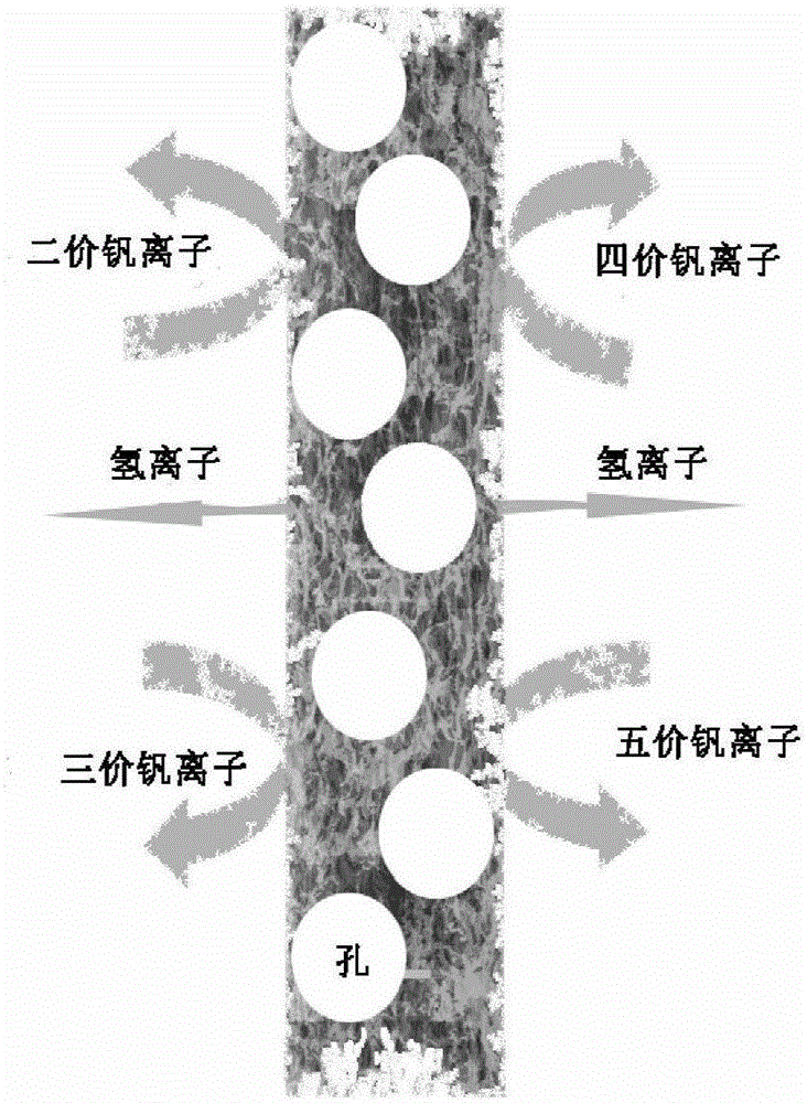
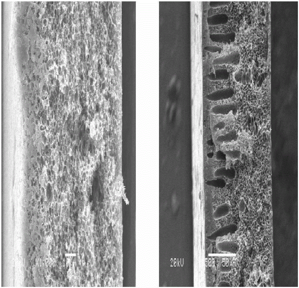
[0039] Dissolve 5 g of polyethersulfone in 15 g of DMAC and stir for 2 hours to form a uniform and transparent polymer solution, which is scraped on a glass plate with a glass rod to a thickness of 200 microns. Then the glass plate together with the resin is quickly placed in an air environment at 50°C and 100% humidity. After 5 minutes, the glass plate was taken out and immersed in 5 L of water to wash the porous membrane. The internal pore diameter of the membrane is about 1um, the membrane surface pore diameter is about 5nm, and the membrane surface porosity is 50%. figure 2 The left shows the cross-sectional SEM picture of the prepared membrane material, showing a regular pore structure. The all-vanadium flow energy storage battery is assembled by using the prepared porous diaphragm, the activated carbon felt is the catalytic layer, the graphite plate is the bipolar plate, and the effective area of ​​the membrane is 9cm -2 , with a current density of 80mAcm -2 , the va...

Embodiment 2

[0044] 7.5 grams of polyacrylonitrile were dissolved in 30mlDMSO+10mlTHF, stirred for 5 hours to form a uniform and transparent polymer solution, and scraped on a glass plate with a glass rod to a thickness of 200 microns. The glass plate together with the resin was then quickly placed in air at 50°C and 40% humidity. After 5 minutes, the glass plate was taken out and immersed in 5 L of water to wash the porous membrane.

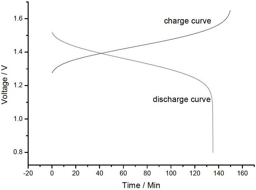
[0045] The all-vanadium flow energy storage battery is assembled by using the prepared porous diaphragm, the activated carbon felt is the catalytic layer, the graphite plate is the bipolar plate, and the effective area of ​​the membrane is 9cm -2 , with a current density of 80mA cm -2 , the vanadium ion concentration in the electrolyte is 1.50mol L -1 , H 2 SO 4 The concentration is 3mol L -1 . The assembled flow battery has a current efficiency of 93.2%, a voltage efficiency of 87%, and an energy efficiency of 81%.

[0046] exist figure 2 Among the...


PUM

PropertyMeasurementUnit
sizeaaaaaaaaaa
thicknessaaaaaaaaaa
porosityaaaaaaaaaa

Abstract

The invention relates to the application of a class of porous diaphragms in liquid flow energy storage batteries. The porous diaphragms are prepared from one or more than two organic polymer resins and then prepared by a gas-phase induced phase conversion method, wherein The gas phase is a poor solvent vapor atmosphere of organic polymer resin. This kind of membrane can effectively realize the separation of ions in different valence states, maintain the ion permeation selectivity of the membrane, and realize the transfer of ions without relying on ion exchange groups. The preparation method of this type of membrane material is simple, the pore structure is controllable, the cost is low, and it is easy to realize mass production, which expands the processing method and selection range of membrane materials for liquid flow energy storage batteries.

Description

technical field [0001] The invention relates to the application of a porous diaphragm in a flow energy storage battery, in particular to the application of this type of membrane in an all-vanadium flow energy storage battery. Background technique [0002] Liquid flow energy storage battery is a new electrochemical energy storage technology. Compared with other energy storage technologies, it has high energy conversion efficiency, flexible system design, large storage capacity, free location selection, deep discharge, safety and environmental protection, and maintenance. With the advantages of low cost, it can be widely used in wind energy, solar energy and other renewable energy generation and energy storage, emergency power system, backup power station and power system peak shaving and valley filling. All-vanadium flow energy storage battery is considered to be the most promising and representative type of flow energy storage battery due to its advantages of high safety, go...

Claims


Application Information

Patent Timeline
Patent Type & Authority Patents(China)
IPC IPC(8): H01M2/16H01M50/403H01M50/411H01M50/463
CPCH01M8/0293Y02E60/50
Inventor 张华民李先锋张洪章段寅琦史丁秦
Owner DALIAN INST OF CHEM PHYSICS CHINESE ACAD OF SCI
Why Eureka
Try Eureka