
Device and method for strengthening sludge digestion and synchronously denitrifying and dephosphorizing

A simultaneous denitrification and dephosphorization and sludge removal technology, applied in chemical instruments and methods, water/sludge/sewage treatment, water/sewage multi-stage treatment, etc., can solve the problem of increasing the solid load of subsequent treatment units and large washing water volume , Sludge-water separation difficulties and other problems, to achieve the effect of weakening substrate inhibition, less sludge production, and stable denitrification effect

Active Publication Date: 2014-04-02
BEIJING UNIV OF TECH
View PDF4 Cites 12 Cited by
  • Summary
  • Abstract
  • Description
  • Claims
  • Application Information

AI Technical Summary

Problems solved by technology

The use of fermentation-elaching process has the following disadvantages in practical application: due to the adsorption of sludge, the separation of mud and water is difficult, the VFA produced by fermentation is difficult to be elutriated, and a higher elutriation efficiency is required. The amount of elutriation water; it is difficult to avoid the occurrence of methanogenic reaction in a complete anaerobic reactor, and the hydrolysis of particulate matter is the rate-limiting step of sludge anaerobic fermentation, so the fermentation product is consumed by methanogenic bacteria in large quantities; in order to achieve a higher elutriation The washing efficiency requires a large amount of elutriation water, which will inevitably produce a large ascending flow rate, which will bring out a lot of particulate matter, thereby increasing the solid load of the subsequent processing unit.

Method used

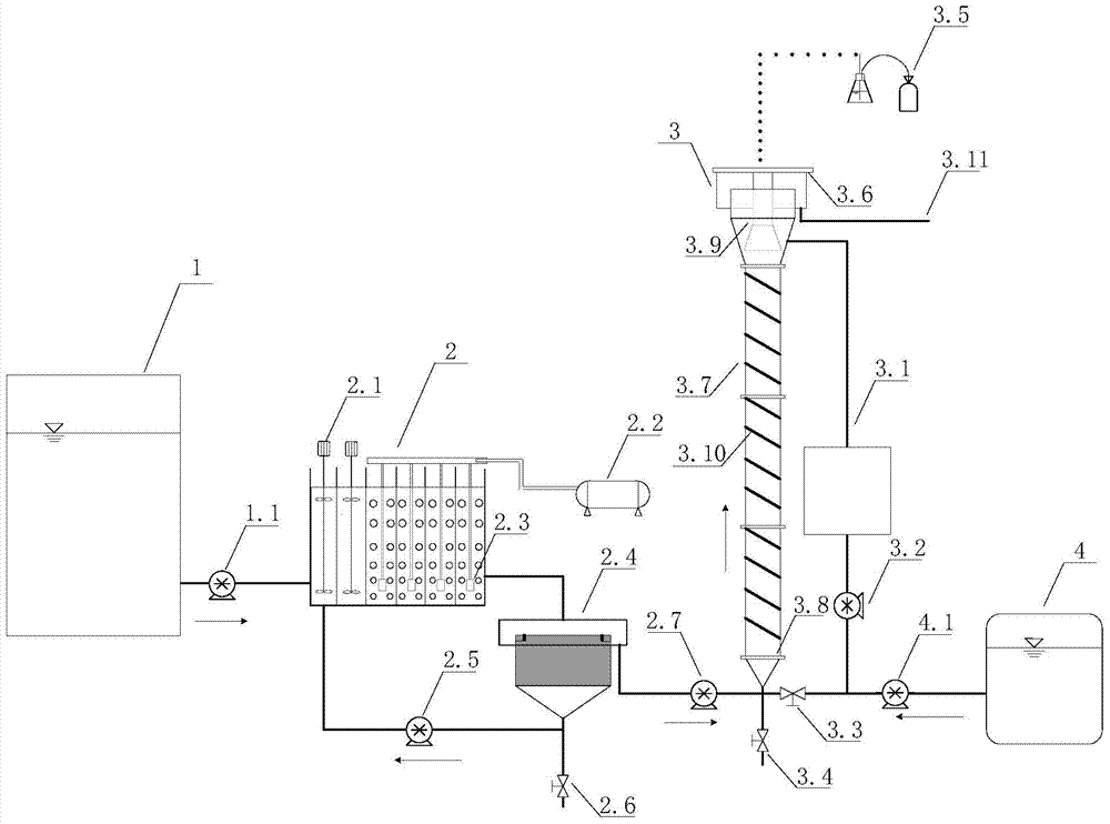

Image

  • Device and method for strengthening sludge digestion and synchronously denitrifying and dephosphorizing
  • Device and method for strengthening sludge digestion and synchronously denitrifying and dephosphorizing
  • Device and method for strengthening sludge digestion and synchronously denitrifying and dephosphorizing

Examples


Embodiment Construction

[0034] The present invention will be described in further detail in conjunction with the accompanying drawings and embodiments.

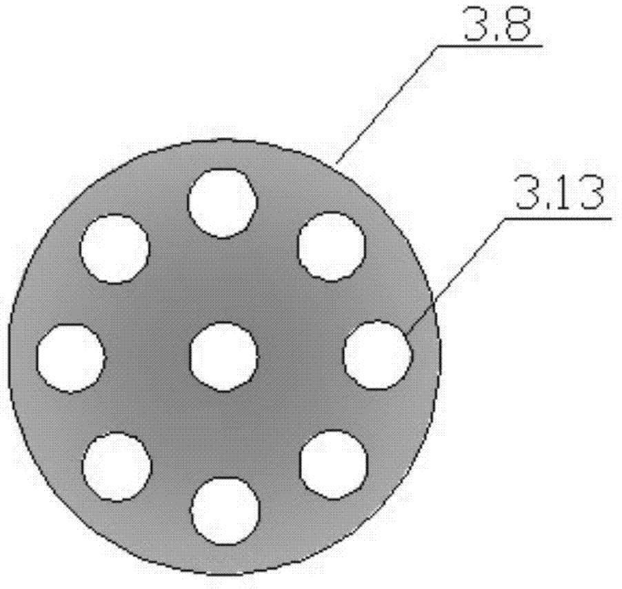
[0035] Such as figure 1 , figure 2 , image 3 As shown, the device for strengthening sludge digestion and synchronous nitrogen and phosphorus removal includes raw water tank 1, raw water inlet pump 1.1, A-O reactor 2, stirring device 2.1, air compressor 2.2, aeration head 2.3, sedimentation tank 2.4, sewage Mud return pump 2.5, mud discharge valve 2.6, outlet pump 2.7, SFDANR reactor 3, intermediate water tank 3.1, circulation pump 3.2, circulation control valve 3.3, emptying valve 3.4, gas collection device 3.5, sealing plate 3.6, cylindrical sewage Mud bed 3.7, water distribution device 3.8, three-phase separator 3.9, heating belt device 3.10, outlet pipe 3.11, sponge filler 3.12, water distribution hole 3.13, mud storage tank 4, mud inlet pump 4.1.

[0036] The raw water tank 1 is connected to the A-O reactor 2 through the raw water inlet pum...


PUM


Abstract

The invention relates to a device and a method for strengthening sludge digestion and synchronously denitrifying and dephosphorizing, and belongs to the technical field of low-carbon-nitrogen-ratio (C / N) and high-concentration ammonia nitrogen wastewater biological denitrification. The device is provided with a raw water tank, an A-O (anaerobic-oxic) reactor, a sedimentation tank, a sludge fermentation, coupling and denitrification synchronization autotrophic denitrification (SFDANR) reactor and a sludge storage tank, wherein the raw water tank is connected with the A-O reactor by a raw water inlet pump; a water outlet of the sedimentation tank is connected with the SFDANR reactor by a water outlet pump; and the SFDANR reactor is provided with a self-circulation pipeline. The method comprises the following steps of starting the A-O reactor, starting the SFDANR reactor, and allowing the A-O reactor and the SFDANR reactor to run in series. The device and the method are suitable for deep denitrification and dephosphorization of high ammonia nitrogen domestic sewage and a sludge digestion solution; a technology is advanced; a sludge yield is reduced effectively; and energy saving and consumption reduction advantages are obvious.

Description

technical field [0001] The invention relates to a device and method for strengthening sludge digestion and synchronously removing nitrogen and phosphorus, and belongs to the technical field of biochemical sewage sludge treatment. The ammonia nitrogen released by sludge fermentation and the nitrite produced by short-range nitrification are removed by anaerobic ammonium oxidation, and the denitrifying bacteria use the volatile organic acids produced by hydrolysis and acidification as electron donors to denitrify the produced nitrate nitrogen to reach total nitrogen Deep removal and effective utilization of sludge. This technology is suitable for the enhanced denitrification and dephosphorization of sewage with low C / N ratio and C / P ratio and the initial reduction and stabilization of sludge. Background technique [0002] In the "Pollutant Discharge Standards for Urban Sewage Treatment Plants" (GB18918-2002) promulgated in 2002 by our country, the first-level A standard requir...

Claims


Application Information

Patent Timeline
IPC IPC(8): C02F9/14
Inventor 彭永臻王博王淑莹马斌金宝丹
Owner BEIJING UNIV OF TECH
Learn More