Rapid in-plane deformation measurement system and measurement method based on space phase shift

A measurement system and space technology, applied in the field of fast space phase shift technology, can solve problems such as the inability to achieve fast measurement

Active Publication Date: 2014-04-02
HEFEI UNIV OF TECH
View PDF2 Cites 18 Cited by
  • Summary
  • Abstract
  • Description
  • Claims
  • Application Information

AI Technical Summary

Problems solved by technology

[0006] The technical problem to be solved by the present invention is to avoid the deficiencies in the above-mentioned prior art, and to provide a rapid measurement system and measurement method for in-plane deformation based on spatial phase shift, so as to meet the requirements of modern high-speed and high-p

Method used


Image

  • Rapid in-plane deformation measurement system and measurement method based on space phase shift
  • Rapid in-plane deformation measurement system and measurement method based on space phase shift
  • Rapid in-plane deformation measurement system and measurement method based on space phase shift

Examples


Embodiment Construction

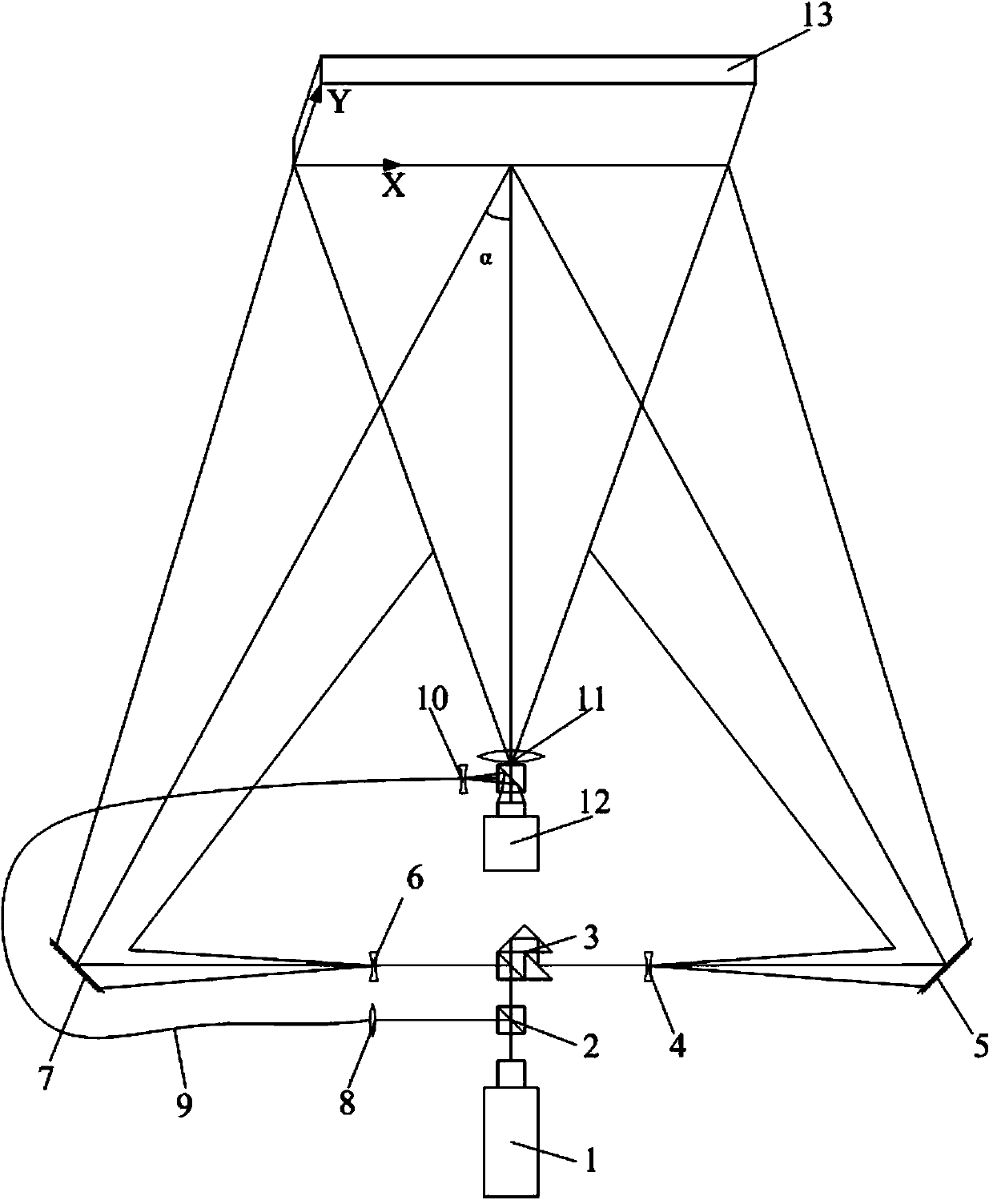
[0040] see figure 1 , the structural form of the rapid measurement system based on spatial phase shift in-plane deformation in this embodiment is:

[0041] The laser 1 is set, and its outgoing light is divided into the first beam and the second beam through the beam splitter 2; the first beam is converged into the carrier optical fiber 9 through the convex lens 8, and the first beam is guided by the carrier optical fiber 9, and passes through the optical fiber The beam expander 10 is irradiated onto the CCD target array of the CCD camera 12 to form a reference light carrier optical path; the second beam of light is divided into two beams of object light through the beam splitting prism group 3, which are respectively the first beam of object light and the second beam of object light. Light, the two beams of object light pass through the first beam expander 4, the first reflector 5, the second beam expander 6, and the second reflector 7 in sequence, respectively, and irradiate ...


PUM


Abstract

The invention discloses a rapid in-plane deformation measurement system and a measurement method based on space phase shift. The measurement system is characterized by consisting of a laser, a beam splitter prism group, a convex lens, a reflector, a beam expander, a carrier optical fiber fine tuning device, a lens imaging device and a CCD (Charge Couple Device) camera collecting device. According to the rapid in-plane deformation measurement system and the measurement method based on space phase shift, the oblique angle of an optical fiber irradiating a CCD array is changed and the space directions are different, the separation of a low frequency carrier and a high frequency speckle is realized, a low frequency item is extracted by Fourier transformation, inverse Fourier transformation is performed on the low frequency item, the phase distribution of an interference wave face representing the object in-plane deformation is obtained, and the real in-plane deformation of an object to be measured is obtained by the subtraction of phase position images before and after loading. The aim of rapid phase position detection is realized by only using a single image in a speckle interference material, the system is simplified, the cost is reduced, and the dynamic high-speed nondestructive measurement of the in-plane deformation is realized.

Description

technical field [0001] The invention relates to a rapid measurement technology of in-plane deformation of speckle interference, especially a rapid spatial phase shift technology, which improves the real-time and timeliness of in-plane measurement of laser speckle interference, and broadens the range of high-speed online detection of laser speckle interference. Applications. It can be widely used in strain and deformation measurement in machinery manufacturing, aerospace, materials and biology. Background technique [0002] Digital Speckle Pattern Interferometry (Digital Speckle Pattern Interferometry, DSPI) is an optical measurement method that integrates laser, electronics and image processing technologies, and has the advantages of high precision, non-contact and full-field measurement. It is widely used in the measurement of machinery manufacturing, aerospace, materials and biology. [0003] In the digital speckle interferometry technology, using the principle of laser ...

Claims


Application Information

Patent Timeline
IPC IPC(8): G01B11/16
Inventor 王永红孙建飞杨连祥
Owner HEFEI UNIV OF TECH
Why Eureka
Try Eureka