
Position loop control-based electric steering engine system

A technology of electric steering gear and ring control, which is applied in three-dimensional position/channel control and other directions, can solve technical difficulties and other problems, and achieve the effects of overcoming parameter dispersion, improving anti-interference ability, and fast response speed

Inactive Publication Date: 2014-04-02
陕西航天导航设备有限公司
View PDF0 Cites 23 Cited by
  • Summary
  • Abstract
  • Description
  • Claims
  • Application Information

AI Technical Summary

Problems solved by technology

[0005] The purpose of the present invention is to provide an electric steering gear system based on position loop control to overcome the technical difficulties faced by the existing traditional missile steering gear

Method used


Image

  • Position loop control-based electric steering engine system
  • Position loop control-based electric steering engine system
  • Position loop control-based electric steering engine system

Examples


Embodiment Construction

[0026] The steering gear system consists of five parts: control circuit, drive circuit, servo motor, deceleration transmission mechanism and feedback unit, see attached figure 1 .

[0027] The steering gear system receives a certain size and polarity of the steering control signal u from the flight controller on the missile i , to control the rotation of the rudder surface. The actual rudder deflection angle δ forms the rudder deflection signal u through the feedback unit f , and the rudder control signal u i Generate error signal u c , the controller controls the error signal u according to the control algorithm c After the signal is amplified by the drive circuit, the servo motor is driven to rotate, and the torque of the servo motor is amplified by the reduction transmission mechanism to drive the rudder to deflect at the required angle, thereby realizing the closed loop of the position loop of the electric rudder control.

[0028] When the error u c When it is posit...


PUM


Abstract

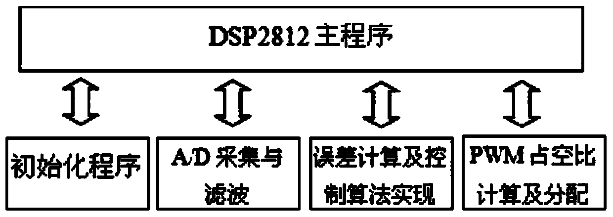
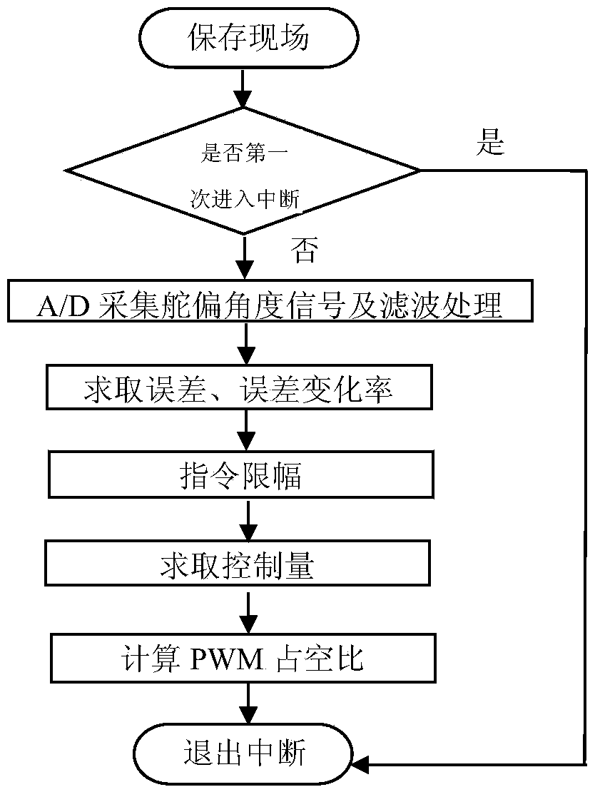
The invention relates to an electric steering engine system, and particularly discloses a position loop control-based electric steering engine system, which is implemented in a way of combining hardware and software. A DC / DC (direct current / direct current) power supply with isolated output is adopted for a power circuit in a hardware design, and missile power is transformed to be supplied to each unit circuit; TMS320F2812 is adopted as a master control unit of a control circuit, and is used for acquiring a rudder control signal and a rudder deflection angle feedback signal, integrating and amplifying errors of the rudder control signal and the rudder deflection angle feedback signal, calculating an actually output PWM (pulse width modulation) signal by using a fuzzy PID (proportion integration differentiation) algorithm, and providing the PWM signal for a driving circuit; the driving circuit is used for performing power amplification on the signal, and driving a steering engine execution mechanism to rotate, thereby realizing closed-position loop control on the electric steering engine system.

Description

technical field [0001] The invention relates to a steering gear system, in particular to an electric steering gear control system. Background technique [0002] The performance of the steering gear control system as an actuator on the projectile directly affects the control quality of the whole projectile control system. [0003] The traditional missile steering gear generally adopts analog, hydraulic or pneumatic servo system, but its structure is complex, the processing precision is high, the mass is high, the cost is high, and the technology is difficult. [0004] With the rapid development of digital signal processing technology, DSP, ARM and CPLD are applied to the electric steering gear control system, which can directly generate high-precision PWM signal to control the motor, has powerful data processing capabilities, and effectively suppresses the torque ripple. It reduces the vibration of the motor and prolongs the life of the motor. At the same time, the dynamic p...

Claims


Application Information

Patent Timeline
Patent Type & Authority Applications(China)
IPC IPC(8): G05D1/10
Inventor 黄朝丽李龙张小凯
Owner 陕西航天导航设备有限公司
Learn More