
Battery cathode material and high temperature solid phase synthesis method

A battery positive electrode, high-temperature solid phase technology, applied in battery electrodes, lithium batteries, chemical instruments and methods, etc., can solve problems such as unsatisfactory electrochemical performance, reduced battery life, and easy disproportionation reactions on the surface of particles

Inactive Publication Date: 2014-04-16
GUANGXI UNIVERSITY OF TECHNOLOGY
View PDF3 Cites 0 Cited by
  • Summary
  • Abstract
  • Description
  • Claims
  • Application Information

AI Technical Summary

Problems solved by technology

[0003] In the solid-phase method, due to insufficient contact between the Li source and the Mn source during the solid-state reaction, the purity of the synthesized product is not high, and the electrochemical performance of the synthesized product is not ideal, especially in the later stage of lithium battery discharge. 3+ The concentration is higher, and the disproportionation reaction is prone to occur on the particle surface: 2Mn 3+ (solid state)→Mn 4+ (solid state)+Mn 2+ (liquid state), the resulting Mn 2+ Soluble in electrolyte, the Taylor effect intensifies
This makes the capacity of the LMO seriously attenuated, reducing the service life of the battery
On the other hand, in the later stage of discharge, due to the uneven precipitation of lithium, there will be protrusions of dendrite structure, which are easy to pierce the separator and cause a short circuit phenomenon, which has great potential safety hazards. Furthermore, the synthesis of LiMn 2 o 4 The conductivity is poor, so that lithium ions cannot be deintercalated and deintercalated normally, and the synthesis of LiMn 2 o 4 Electrochemical performance is not ideal when charging and discharging at high current
The LMO synthesized in the liquid phase method will also be purely dissolved in Mn, causing capacity decay and battery life reduction

Method used


Image

  • Battery cathode material and high temperature solid phase synthesis method
  • Battery cathode material and high temperature solid phase synthesis method
  • Battery cathode material and high temperature solid phase synthesis method

Examples


Embodiment Construction

[0024] The preferred embodiments of the present invention will be described below in conjunction with the accompanying drawings. It should be understood that the preferred embodiments described here are only used to illustrate and explain the present invention, and are not intended to limit the present invention.

[0025] A battery positive electrode material, its chemical formula is LiLa 0.1 co 0.1 mn 1.8 o 4 .

[0026] The high-temperature solid-phase synthesis method of the above-mentioned battery cathode material,

[0027] 1) Preparation of cathode material:

[0028] A. The hydroxide of lithium, the oxide of manganese, the oxide of Co and the oxide of La are according to the amount ratio n(Li):n(Mn):n(La):n(Co)=1.01 : 1.8: 0.1: 0.1 Weigh and grind in a planetary ball mill for 0.2-2 hours;

[0029] B. Completely dissolve the ball-milled lithium source in citric acid, and then stir for 0.1-2 hours, slowly add a small amount of Mn source, Co oxide, and La oxide, and...


PUM


Abstract

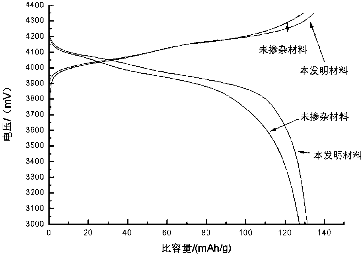
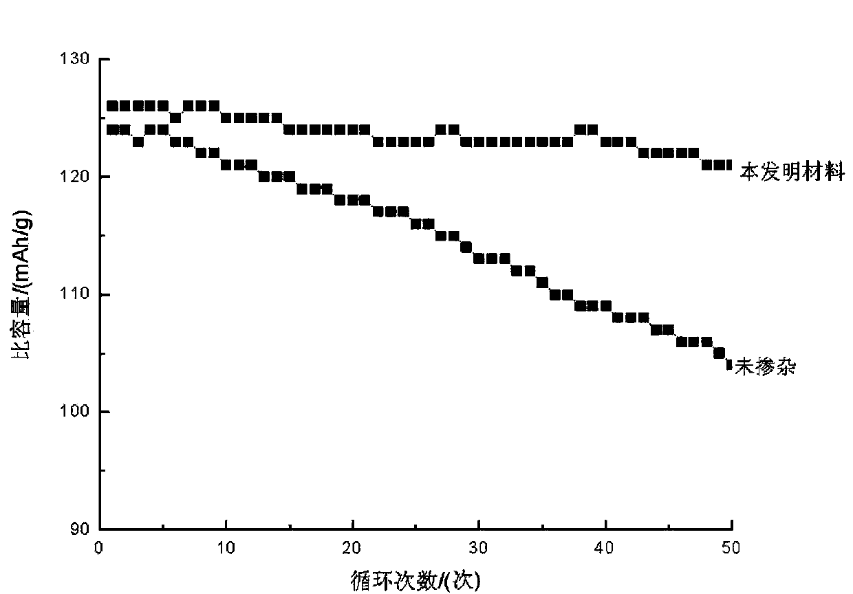
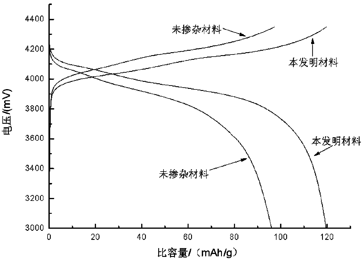
The invention discloses a battery cathode material of which the chemical formula is LiLa0.1 Co0.1 Mn1.8 O4. The spinel structure of the battery cathode material LiLa0.1 Co0.1 Mn1.8 O4 provided by the invention has low probability of being damaged after the mixing of Co ions, the electrical conductivity of a synthetic material is enhanced, a diffusion coefficient is increased to 2.4*10<-12> - 1.4*10<-11> m<2> / s from 9.2*10<-14> - 2.6*10<-12> m<2> / s, so as to be convenient for lithium-ion taking off and embedding, after the addition of LA ions, part of Mn ions can be replaced, in a later period of slight discharging, the concentration of Mn<+3> ions is lower, disproportionation reaction is prevented, dendritic crystal forming on the surface of a positive pole is avoided, a diaphragm is pierced, and the safety performance is improved. The synthetic material adopts a spinel structure. The synthetic material is more superior in cycle performance.

Description

technical field [0001] The invention relates to a battery cathode material. Background technique [0002] Synthesis of LiMn by High Temperature Solid State Method 2 o 4 It is a method commonly used by battery companies now. The synthesis conditions and process of this method are simple and easy to control. The synthesized product is a spinel LMO structure with a specific capacity of 125mAh / g. The traditional solid-phase synthesis method uses lithium hydroxide (or carbonic acid Salt, nitrate) and manganese oxides (carbonate, hydroxide) are fully mixed and calcined at high temperature to synthesize. [0003] In the solid-phase method, due to insufficient contact between the Li source and the Mn source during the solid-state reaction, the purity of the synthesized product is not high, and the electrochemical performance of the synthesized product is not ideal, especially in the later stage of lithium battery discharge. 3+ The concentration is higher, and the disproportionati...

Claims


Application Information

Patent Timeline
IPC IPC(8): H01M4/505C01G45/00
CPCY02E60/122C01G45/006H01M4/1391H01M4/362H01M4/505H01M4/525H01M10/052Y02E60/10
Inventor 梁兴华曾帅波刘于斯史琳叶超超刘天骄华晓鸣宋清清刘浩
Owner GUANGXI UNIVERSITY OF TECHNOLOGY
Learn More