Stirling generator of using afterheat to desalinate seawater

A generator and Stirling technology, applied in the field of Stirling generators, can solve the problems such as the integration of power supply and water supply technology, and achieve the effects of high heat engine strengthening, small vibration and low temperature

Active Publication Date: 2014-04-23
山西三晋之窗商务服务有限公司
View PDF8 Cites 2 Cited by
  • Summary
  • Abstract
  • Description
  • Claims
  • Application Information

AI Technical Summary

Problems solved by technology

The construction of island infrastructure urgently needs power and water cogeneration equipment, but so far, there is no feasible integrated power and water supply technology

Method used


Image

  • Stirling generator of using afterheat to desalinate seawater

Examples


Embodiment 1

[0016] Embodiment 1 is an application example of using fuel combustion as a heat source, and Embodiment 2 is an application example of using a nuclear reactor as a heat source in a nuclear submarine.

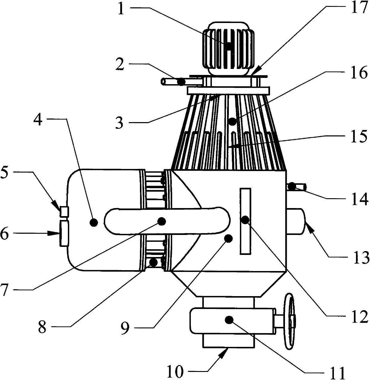
[0017] Embodiment 1: A combustion chamber is set at the heat inflow end, and the heat released at the heat outflow end and the waste heat of the combustion exhaust gas at the heat inflow end heat seawater in the seawater evaporation tank. figure 1 It is a structural schematic diagram of Example 1. The Stirling generator is a double-loop connection type with 6 working chambers and has 3 heat exchange regenerators. The end face of the heat inflow end 4 has a fuel inlet 5 and a combustion air inlet 6, and the combustion chamber in the heat inflow end 4 has a heat inflow end cylinder and a connecting pipe between the cylinder and the regenerator. The regenerator 8 is placed between the heat inflow end and the heat outflow end. The cylinder at the heat outflow end and the connecting...

Embodiment 2

[0019] Embodiment 2: The nuclear submarine space is closed and narrow, and the circulating air of desalinated seawater must be cooled as soon as possible. Because the nuclear reactor directly supplies heat at the heat inflow end, the heat released at the heat outflow end heats the seawater in the seawater evaporation tank. Therefore, on the basis of Example 1, two corresponding changes are made to the structure: one is to place the heat inflow end cylinder and the connecting pipe between the cylinder and the regenerator in the heating device of the nuclear reactor, and cancel the combustion exhaust pipe; the other is to install seawater cooling fresh water The seawater circulation device of the cooling fins on the surface of the condenser has a structure in which the cooling fins are made into a spiral shape, and the air flow channels and the sea water flow channels are arranged alternately.

[0020] Its working process is: connect the seawater inflow pipe, inject seawater int...


PUM


Abstract

The invention provides a stirling generator of using afterheat to desalinate seawater. A reversible stirling heat engine is applied as a generator; a heat flow-in end is arranged in a heat source; heat flow-out ends are arranged on a fresh water condenser and a seawater evaporation tank; the fresh water condenser is arranged on the seawater evaporation tank; an annular fresh water collecting tank is arranged at the bottom inside the fresh water condenser; a fresh water flow-out pipe inlet is connected to the bottom of the fresh water collecting tank; cooling fins are distributed on the side surface of the fresh water condenser; an air entering flue at the center of the fresh water condenser is communicated with a fresh water condensation flue of an annular space out of the center of the fresh water condenser to form an air circulating flue; a fan is arranged at an air inlet of the air flue; an air outlet of the air flue is annular, is opened downward and faces to the cooling fins. A sea salt exhaust port is formed in the bottom of the seawater evaporation tank; a sea salt exhaust valve is arranged. The stirling generator is high in heat engine intensifying degree in seawater cooling, and high in heat engine efficiency, and can be widely applied to vessels and island infrastructures by electricity-water cogeneration, and the comprehensive performance indexes of a nuclear submarine and an aircraft carrier can be greatly improved.

Description

Technical field [0001] The invention relates to a Stirling generator, in particular to a Stirling generator for desalinating seawater by using waste heat. Background technique [0002] Marine power and fresh water supply are two major problems restricting human ocean voyages. Marine power has used thermal engines such as steam engines, steam turbines, old-fashioned Stirling engines, gas turbines, and internal combustion engines. The modern marine power management mode is changing from the mechanical power mode to the electric mode. The heat engine converts heat energy into electrical energy and then drives the ship to sail. In the past, the amount of fresh water that a ship could store determined its voyage, and fresh water had to be replenished in due course during the voyage. Today, modern seawater desalination technology can install seawater desalination devices on board to solve the problem of fresh water supply. However, factors such as high energy consumption, high ...

Claims


Application Information

Patent Timeline
Patent Type & Authority Applications(China)
IPC IPC(8): C02F1/16F02G1/043C02F103/08
CPCY02A20/124Y02A20/141
Inventor 孔令斌
Owner 山西三晋之窗商务服务有限公司
Why Eureka
Try Eureka